 |
Matronics Email Lists
Web Forum Interface to the Matronics Email Lists
|
| View previous topic :: View next topic |
| Author |
Message |
HBaker
Joined: 16 Nov 2008
Posts: 119
|
 Posted: Sun Sep 27, 2009 4:48 pm Post subject: Booster coil Posted: Sun Sep 27, 2009 4:48 pm Post subject: Booster coil |
 |
|
Can anyone send me some pics of where the wires hook up in side the mag? I think the left one? Like the high voltage wire and  I assume there is a power supply to it,But what about the wires or wire to the  P lead or something?


Cheers Henry
| | - The Matronics M14PEngines-List Email Forum - | | | Use the List Feature Navigator to browse the many List utilities available such as the Email Subscriptions page, Archive Search & Download, 7-Day Browse, Chat, FAQ, Photoshare, and much more:
http://www.matronics.com/Navigator?M14PEngines-List |
|
_________________
Currently building a Murphy Moose - any help would be appreciated. |
|
| Back to top |
|
 |
george(at)gesoco.com
Guest
|
| Posted: Tue Sep 29, 2009 7:44 am Post subject: Booster coil |
|
|
Please see the attached service bulletin. It has pix of how to do it.

George Coy

CAS Ltd.

714 Airport Rd.

Swanton VT 05488

802-868-5633 off

802-363-5782 cell

george.coy(at)gmail.com

http://coyafct.com/

SKYPE george.coy


--
| | - The Matronics M14PEngines-List Email Forum - | | | Use the List Feature Navigator to browse the many List utilities available such as the Email Subscriptions page, Archive Search & Download, 7-Day Browse, Chat, FAQ, Photoshare, and much more:
http://www.matronics.com/Navigator?M14PEngines-List |
|
| Description: |
|

Download |
| Filename: |
SPK01_service_bulletin_FINAL_(2).pdf |
| Filesize: |
969.02 KB |
| Downloaded: |
1245 Time(s) |
|
|
| Back to top |
|
|
HBaker
Joined: 16 Nov 2008
Posts: 119
|
| Posted: Thu Oct 01, 2009 5:15 pm Post subject: Re: Booster coil |
|
|
George


I have the old type, and I could not find how to hook it up in the manual anywhere .


Henry
| | - The Matronics M14PEngines-List Email Forum - | | | Use the List Feature Navigator to browse the many List utilities available such as the Email Subscriptions page, Archive Search & Download, 7-Day Browse, Chat, FAQ, Photoshare, and much more:
http://www.matronics.com/Navigator?M14PEngines-List |
|
_________________
Currently building a Murphy Moose - any help would be appreciated. |
|
| Back to top |
|
|
george(at)gesoco.com
Guest
|
| Posted: Fri Oct 02, 2009 6:54 am Post subject: Booster coil |
|
|
Henry, the service bulletin I sent shows how to put the high tension wire

into the magneto. You need to tell me if you have a Russian unit or one of

the T-6 units. The Russian unit has two wires the high tension lead out of

the unit and a wire into the unit that applies 28 volts when are pressing

the start button.  I do not know anything about the T-6 units but they

should not be difficult to figure out. They all work the same way.

George Coy

CAS Ltd.

714 Airport Rd.

Swanton VT 05488

802-868-5633 off

802-363-5782 cell

george.coy(at)gmail.com

http://coyafct.com/

SKYPE george.coy


--
| | - The Matronics M14PEngines-List Email Forum - | | | Use the List Feature Navigator to browse the many List utilities available such as the Email Subscriptions page, Archive Search & Download, 7-Day Browse, Chat, FAQ, Photoshare, and much more:
http://www.matronics.com/Navigator?M14PEngines-List |
|
|
|
| Back to top |
|
|
HBaker
Joined: 16 Nov 2008
Posts: 119
|
| Posted: Fri Jan 01, 2010 6:09 pm Post subject: Re: Booster coil |
|
|
Thanks for the info.


What I really need to know is where the P leads wire enters the mag case and where the wire connects inside.  Also need to know where the p-lead ground shield should connect on the mag.


Thanks,


Henry
| | - The Matronics M14PEngines-List Email Forum - | | | Use the List Feature Navigator to browse the many List utilities available such as the Email Subscriptions page, Archive Search & Download, 7-Day Browse, Chat, FAQ, Photoshare, and much more:
http://www.matronics.com/Navigator?M14PEngines-List |
|
_________________
Currently building a Murphy Moose - any help would be appreciated. |
|
| Back to top |
|
|
dsavarese0812(at)bellsout
Guest
|
| Posted: Fri Jan 01, 2010 6:23 pm Post subject: Booster coil |
|
|
The P leads are at the back end of the mag closest to the  firewall.  The P lead is a knurled nut with a semi-circular locking spring  clip holding it in place.  When you remove the P lead from the mag you will  see where and how the shield is soldered to the inner section of the knurled  nut.  The other end of the P lead goes directly to the mag switch.   You can make a continuity check with an ohm meter from the P lead to the mag  switch position 1 or 2.  Position 1 is the left mag.

 Dennis


 [quote]   ---
| | - The Matronics M14PEngines-List Email Forum - | | | Use the List Feature Navigator to browse the many List utilities available such as the Email Subscriptions page, Archive Search & Download, 7-Day Browse, Chat, FAQ, Photoshare, and much more:
http://www.matronics.com/Navigator?M14PEngines-List |
|
|
|
| Back to top |
|
|
HBaker
Joined: 16 Nov 2008
Posts: 119
|
| Posted: Fri Jan 01, 2010 6:51 pm Post subject: Re: Booster coil |
|
|
Thanks again for your reply I see now where it enters the mag but this is a new installation. How and where does the shielded wire connect inside the mag??


Thanks Henry Moose 294
| | - The Matronics M14PEngines-List Email Forum - | | | Use the List Feature Navigator to browse the many List utilities available such as the Email Subscriptions page, Archive Search & Download, 7-Day Browse, Chat, FAQ, Photoshare, and much more:
http://www.matronics.com/Navigator?M14PEngines-List |
|
_________________
Currently building a Murphy Moose - any help would be appreciated. |
|
| Back to top |
|
|
dsavarese0812(at)bellsout
Guest
|
| Posted: Fri Jan 01, 2010 6:58 pm Post subject: Booster coil |
|
|
It doesn't connect inside the mag.  It connects via the  knurled knob which holds the part that inserts into the mag.  Do you have  new mags and do they have the knurled knobs on the back end of the mag?  If  you'll wait until tomorrow, I'll try to take a picture of the knurled knob and  the P-lead and email it to you.  If you don't have new mags that have the  knurled knobs screwed into them, you'll need to order 2 assemblies from either  Doug Sapp or Jill at M14P.


 Maybe Doug has a drawing or photo of the knurled knob and  parts that screw into the mag?

 Dennis


 [quote]   ---
| | - The Matronics M14PEngines-List Email Forum - | | | Use the List Feature Navigator to browse the many List utilities available such as the Email Subscriptions page, Archive Search & Download, 7-Day Browse, Chat, FAQ, Photoshare, and much more:
http://www.matronics.com/Navigator?M14PEngines-List |
|
|
|
| Back to top |
|
|
HBaker
Joined: 16 Nov 2008
Posts: 119
|
| Posted: Fri Jan 01, 2010 7:11 pm Post subject: Re: Booster coil |
|
|
Thanks again


Yes I do have the new mags  and I know the knurled knob you are talking about. I looked inside and saw  cap like a tire valve cap.  Still confused though. a pic would be great. The center connector of the shielded wire would be soldered in place???

Henry
| | - The Matronics M14PEngines-List Email Forum - | | | Use the List Feature Navigator to browse the many List utilities available such as the Email Subscriptions page, Archive Search & Download, 7-Day Browse, Chat, FAQ, Photoshare, and much more:
http://www.matronics.com/Navigator?M14PEngines-List |
|
_________________
Currently building a Murphy Moose - any help would be appreciated. |
|
| Back to top |
|
|
dsavarese0812(at)bellsout
Guest
|
| Posted: Fri Jan 01, 2010 7:29 pm Post subject: Booster coil |
|
|
Ahh!  You solder the wire to the inside of the cap that  looks like the tire valve cap.  The shield gets soldered to the insulated  ring that goes around the cap.  The knurled knob touches the insulated ring  and the shield is grounded to the mag case when the knurled knob is screwed into  the mag.

 Dennis


 [quote]   ---
| | - The Matronics M14PEngines-List Email Forum - | | | Use the List Feature Navigator to browse the many List utilities available such as the Email Subscriptions page, Archive Search & Download, 7-Day Browse, Chat, FAQ, Photoshare, and much more:
http://www.matronics.com/Navigator?M14PEngines-List |
|
|
|
| Back to top |
|
|
HBaker
Joined: 16 Nov 2008
Posts: 119
|
| Posted: Fri Jan 01, 2010 7:40 pm Post subject: Re: Booster coil |
|
|
OK, Thanks !

That makes sense now.  I'll take a closer look at this in the morning.


How about the booster coil ?  Power to the 2 nut stud and the case is already grounded ?
| | - The Matronics M14PEngines-List Email Forum - | | | Use the List Feature Navigator to browse the many List utilities available such as the Email Subscriptions page, Archive Search & Download, 7-Day Browse, Chat, FAQ, Photoshare, and much more:
http://www.matronics.com/Navigator?M14PEngines-List |
|
_________________
Currently building a Murphy Moose - any help would be appreciated. |
|
| Back to top |
|
|
dsavarese0812(at)bellsout
Guest
|
| Posted: Fri Jan 01, 2010 7:54 pm Post subject: Booster coil |
|
|
Booster coil - yes, I believe you are correct.  I just  don't remember without looking at one.

 Dennis

 [quote]   ---
| | - The Matronics M14PEngines-List Email Forum - | | | Use the List Feature Navigator to browse the many List utilities available such as the Email Subscriptions page, Archive Search & Download, 7-Day Browse, Chat, FAQ, Photoshare, and much more:
http://www.matronics.com/Navigator?M14PEngines-List |
|
|
|
| Back to top |
|
|
yakplt(at)yahoo.com
Guest
|
| Posted: Sat Jan 02, 2010 4:28 pm Post subject: Booster coil |
|
|
The booster coil has two screw in connectors.  One for the main output voltage which

 takes a rather special piece that sits down in the socket and makes contact with the

 high voltage winding on the coil.  This piece looks very close to the "cigarette" that is

 installed in the mag itself for almost the same purpose.  This piece is held on with a

 screw on threaded cap.


 The input voltage to the boost coil is fed in on the END of the unit.  It too has a threaded

 on piece that is used to ground the shield, with a fitting that is almost exactly the same

 as that which screws on to the OUTSIDE of the mag that Dennis was talking about

 earlier.  Just to be clear ... on that former subject..... one does not take the mag apart

 to get to ANYTHING inside the mag to connect the P Lead wire.   The mag stays

 closed with the top screwed down.  You never go inside of it.  Instead you have a

 special piece that is soldered onto the end of the shielded P lead wire.  This special

 piece then slides into a HOLE on the back of the mag.  Again, you do not take

 anything apart to get at this.  This special phenolic piece slides in and makes contact

 with an internal piece of spring metal.  Then the CAP SCREW is tightened down to

 hold this piece in place.  The shield of the P lead is soldered to the CAP SCREW

 PIECE and is grounded when you tighten the connector down.  Doing this right is

 CRITICAL to avoid severe radio noise.  I mean SEVERE.


 The boost coil is the same way.  The high voltage lead must be shielded and the shield

 grounded at the special connector.  Otherwise the boost coil starting wire will act as a

 very nice antenna even when not starting, and your radios will be next to useless.


 To attach the actual power leads (as Dennis said: 24 vdc) to the coil, you need to

 split the case of the boost coil in half.  (remove the 4 screws on the side after un-

 bending the locking tabs).


 Inside you will see a terminal right next to a black knurled knob that is used to

 adjust the point gap on the buzzer that makes the thing work to begin with.  That

 is your GROUND connection.  As you are looking at the thing face on, with that

 terminal facing you, you will see the black adjustment knob on the left, then going

 clockwise you will see the double-nutted terminal that is the GROUND.  Going

 further clockwise you will see a terminal that is stand alone.  It is hooked to

 nothing else electrically.  All by itself.  That is the main 28 vdc power input

 connection.  Going further around (about 5 o'clock now) you will see a nut

 that connects to the buzzer leaf spring) .  Leave that alone.


 The unit does not get it's ground from the case.


 Best Regards,


 Mark Bitterlich


 p.s.  Be very careful if you don't have the right connection fittings and you decide

 to wire it up as best you can.  Especially the P lead on the mag.  I have seen

 (personally) radio receiver front ends blown from the noise the mag can create

 if the P lead shield is not right.   Good luck.


--- On Fri, 1/1/10, A. Dennis Savarese <dsavarese0812(at)bellsouth.net> wrote:


 [quote]

From: A. Dennis Savarese <dsavarese0812(at)bellsouth.net>

Subject: Re: Re: Booster coil

To: m14pengines-list(at)matronics.com

Date: Friday, January 1, 2010, 10:54 PM


    Booster coil - yes, I believe you are correct.  I just don't remember without looking at one.

 Dennis

 [quote] ---
| | - The Matronics M14PEngines-List Email Forum - | | | Use the List Feature Navigator to browse the many List utilities available such as the Email Subscriptions page, Archive Search & Download, 7-Day Browse, Chat, FAQ, Photoshare, and much more:
http://www.matronics.com/Navigator?M14PEngines-List |
|
|
|
| Back to top |
|
|
yakplt(at)yahoo.com
Guest
|
| Posted: Sat Jan 02, 2010 4:39 pm Post subject: Booster coil |
|
|
One last comment.  Since you are building a Moose, it is very likely that you have

 the engine in hand, (thus the questions) along with the Boost Coil, but you do not

 have the special Russian wiring pieces that connect to them.  Those pieces are

 typically part of the original Russian or Chinese wiring harness.  I suggest that you

 try to get these very special piece/parts so that you can duplicate the original set-up.


 Mark


--- On Sat, 1/2/10, Yak Pilot <yakplt(at)yahoo.com> wrote:


 [quote]

From: Yak Pilot <yakplt(at)yahoo.com>

Subject: Re: M14PEngines-List: Re: Booster coil

To: m14pengines-list(at)matronics.com

Date: Saturday, January 2, 2010, 7:28 PM


      The booster coil has two screw in connectors.  One for the main output voltage which

 takes a rather special piece that sits down in the socket and makes contact with the

 high voltage winding on the coil.  This piece looks very close to the "cigarette" that is

 installed in the mag itself for almost the same purpose.  This piece is held on with a

 screw on threaded cap.


 The input voltage to the boost coil is fed in on the END of the unit.  It too has a threaded

 on piece that is used to ground the shield, with a fitting that is almost exactly the same

 as that which screws on to the OUTSIDE of the mag that Dennis was talking about

 earlier.  Just to be clear ... on that former subject..... one does not take the mag apart

 to get to ANYTHING inside the mag to connect the P Lead wire.   The mag stays

 closed with the top screwed down.  You never go inside of it.  Instead you have a

 special piece that is soldered onto the end of the shielded P lead wire.  This special

 piece then slides into a HOLE on the back of the mag.  Again, you do not take

 anything apart to get at this.  This special phenolic piece slides in and makes contact

 with an internal piece of spring metal.  Then the CAP SCREW is tightened down to

 hold this piece in place.  The shield of the P lead is soldered to the CAP SCREW

 PIECE and is grounded when you tighten the connector down.  Doing this right is

 CRITICAL to avoid severe radio noise.  I mean SEVERE.


 The boost coil is the same way.  The high voltage lead must be shielded and the shield

 grounded at the special connector.  Otherwise the boost coil starting wire will act as a

 very nice antenna even when not starting, and your radios will be next to useless.


 To attach the actual power leads (as Dennis said: 24 vdc) to the coil, you need to

 split the case of the boost coil in half.  (remove the 4 screws on the side after un-

 bending the locking tabs).


 Inside you will see a terminal right next to a black knurled knob that is used to

 adjust the point gap on the buzzer that makes the thing work to begin with.  That

 is your GROUND connection.  As you are looking at the thing face on, with that

 terminal facing you, you will see the black adjustment knob on the left, then going

 clockwise you will see the double-nutted terminal that is the GROUND.  Going

 further clockwise you will see a terminal that is stand alone.  It is hooked to

 nothing else electrically.  All by itself.  That is the main 28 vdc power input

 connection.  Going further around (about 5 o'clock now) you will see a nut

 that connects to the buzzer leaf spring) .  Leave that alone.


 The unit does not get it's ground from the case.


 Best Regards,


 Mark Bitterlich


 p.s.  Be very careful if you don't have the right connection fittings and you decide

 to wire it up as best you can.  Especially the P lead on the mag.  I have seen

 (personally) radio receiver front ends blown from the noise the mag can create

 if the P lead shield is not right.   Good luck.


--- On Fri, 1/1/10, A. Dennis Savarese <dsavarese0812(at)bellsouth.net> wrote:


 [quote]

From: A. Dennis Savarese <dsavarese0812(at)bellsouth.net>

Subject: Re: Re: Booster coil

To: m14pengines-list(at)matronics.com

Date: Friday, January 1, 2010, 10:54 PM


    Booster coil - yes, I believe you are correct.  I just don't remember without looking at one.

 Dennis

 [quote] ---
| | - The Matronics M14PEngines-List Email Forum - | | | Use the List Feature Navigator to browse the many List utilities available such as the Email Subscriptions page, Archive Search & Download, 7-Day Browse, Chat, FAQ, Photoshare, and much more:
http://www.matronics.com/Navigator?M14PEngines-List |
|
|
|
| Back to top |
|
|
george(at)gesoco.com
Guest
|
| Posted: Mon Jan 04, 2010 9:22 am Post subject: Booster coil |
|
|
Mark, I guess I am confused by your explanation.. Perhaps you are  talking about CJ mags and I am not familiar with them. I will post today on the

 motorstarna.com  website the SPK-01 service bulletin.It is  too big to meet the guidelines for posting on the maltronics  site.

      It shows in pictures and words the  instillation of the wires at the magneto end. It is absolutely necessary to  remove the mag cap and rotor cap to thread the high tension lead into the  magneto.  I believe that you are also talking about connections to the  Russian (and maybe Chinese) type  booster coil. I believe that many people  are using the T6 type of booster coils which are very different as well.   They can be de-tuned to run on 12 volts. We also now produce a solid state  "boozer coil" called the SPK-01 that runs on any voltage form 9V to  32V.


 George Coy

 CAS Ltd.

 714 Airport Rd.

 Swanton VT 05488

 802-868-5633 off

 802-363-5782 cell

 george.coy(at)gmail.com (george.coy(at)gmail.com)

 http://coyafct.com/[url=http://coyacft.com/][/url]

 SKYPE george.coy


   From:  owner-m14pengines-list-server(at)matronics.com  [mailto:owner-m14pengines-list-server(at)matronics.com] On Behalf Of Yak  Pilot

Sent: Saturday, January 02, 2010 7:28 PM

To:  m14pengines-list(at)matronics.com

Subject: Re: Re:  Booster coil


                   The booster coil has two screw in connectors.  One for the main        output voltage which

       takes a rather special piece that sits down in the socket and makes        contact with the

       high voltage winding on the coil.  This piece looks very close        to the "cigarette" that is

       installed in the mag itself for almost the same purpose.  This        piece is held on with a

       screw on threaded cap.


       The input voltage to the boost coil is fed in on the END of the        unit.  It too has a threaded

       on piece that is used to ground the shield, with a fitting that is        almost exactly the same

       as that which screws on to the OUTSIDE of the mag that Dennis was        talking about

       earlier.  Just to be clear ... on that former subject..... one        does not take the mag apart

       to get to ANYTHING inside the mag to connect the P Lead        wire.   The mag stays

       closed with the top screwed down.  You never go inside of        it.  Instead you have a

       special piece that is soldered onto the end of the shielded P lead        wire.  This special

       piece then slides into a HOLE on the back of the mag.  Again,        you do not take

       anything apart to get at this.  This special phenolic piece        slides in and makes contact

       with an internal piece of spring metal.  Then the CAP SCREW is        tightened down to

       hold this piece in place.  The shield of the P lead is soldered        to the CAP SCREW

       PIECE and is grounded when you tighten the connector down.         Doing this right is

       CRITICAL to avoid severe radio noise.  I mean SEVERE.


       The boost coil is the same way.  The high voltage lead must be        shielded and the shield

       grounded at the special connector.  Otherwise the boost coil        starting wire will act as a

       very nice antenna even when not starting, and your radios will be        next to useless.


       To attach the actual power leads (as Dennis said: 24 vdc) to the        coil, you need to

       split the case of the boost coil in half.  (remove the 4 screws        on the side after un-

       bending the locking tabs).


       Inside you will see a terminal right next to a black knurled        knob that is used to

       adjust the point gap on the buzzer that makes the thing work to begin        with.  That

       is your GROUND connection.  As you are looking at the thing face        on, with that

       terminal facing you, you will see the black adjustment knob on the        left, then going

       clockwise you will see the double-nutted terminal that is the        GROUND.  Going

       further clockwise you will see a terminal that is stand alone.         It is hooked to

       nothing else electrically.  All by itself.  That is the        main 28 vdc power input

       connection.  Going further around (about 5 o'clock now) you will        see a nut

       that connects to the buzzer leaf spring) .  Leave that        alone.


       The unit does not get it's ground from the case.


       Best Regards,


       Mark Bitterlich


       p.s.  Be very careful if you don't have the right connection        fittings and you decide

       to wire it up as best you can.  Especially the P lead on the        mag.  I have seen

       (personally) radio receiver front ends blown from the noise the mag        can create

       if the P lead shield is not right.   Good luck.


--- On Fri, 1/1/10, A. Dennis Savarese        <dsavarese0812(at)bellsouth.net> wrote:


       [quote]

From:          A. Dennis Savarese <dsavarese0812(at)bellsouth.net>

Subject: Re:          Re: Booster coil

To:          m14pengines-list(at)matronics.com

Date: Friday, January 1, 2010, 10:54          PM


                            Booster coil - yes, I believe you are correct.  I          just don't remember without looking at one.

         Dennis

         [quote]           ---
| | - The Matronics M14PEngines-List Email Forum - | | | Use the List Feature Navigator to browse the many List utilities available such as the Email Subscriptions page, Archive Search & Download, 7-Day Browse, Chat, FAQ, Photoshare, and much more:
http://www.matronics.com/Navigator?M14PEngines-List |
|
|
|
| Back to top |
|
|
mark.bitterlich(at)navy.m
Guest
|
| Posted: Mon Jan 04, 2010 10:45 am Post subject: Booster coil |
|
|
George,


If you were confused by my reply, then it obviously was not good enough.

Sorry!   I was talking about M-14 Booster Coils for the Yaks.


We were talking about two things:


1.  The actual electrical connections to the Booster (Shower of

Sparks... Whatever you want to call it) coil that is external to the

mag.  That coil has the high voltage lead that goes into the MAG for

starting... Goes to the retarded point in the rotor as I am sure you

know!  Also talking about the 28 vdc hookup to that coil.  Power to

which is supplied when you push the starter button.


2.  Where the P lead actually connects to the MAG (on the side, with the

screw in connector).


You're right, some people are indeed using the T6 (and other type)

coils.  I have no personal experience at all with those.  My comments

were focused on just the Chinese and Russian Starting Booster Coils.


I'd like to hear more about your SPK-01 ~!!!!~

Mark


--
| | - The Matronics M14PEngines-List Email Forum - | | | Use the List Feature Navigator to browse the many List utilities available such as the Email Subscriptions page, Archive Search & Download, 7-Day Browse, Chat, FAQ, Photoshare, and much more:
http://www.matronics.com/Navigator?M14PEngines-List |
|
|
|
| Back to top |
|
|
HBaker
Joined: 16 Nov 2008
Posts: 119
|
| Posted: Tue Jan 05, 2010 10:41 am Post subject: Re: Booster coil |
|
|
Thanks guys


I think I have the Mag thing figured out, but to be absolutely sure see if I have this right . The "P" lead wire coming from your mag switch enters at the rear of the mag through the knurled knob you remove the knurled knob and remove  the tire like cap on the end. Peel back the outer braided shield wire push the center wire through and solder it on, then screw the 'tire like ' valve cap back on .Then take the outer braided shielded wire and wrap it around the treads on the knurled knob screw it on and flip the lock spring.
| | - The Matronics M14PEngines-List Email Forum - | | | Use the List Feature Navigator to browse the many List utilities available such as the Email Subscriptions page, Archive Search & Download, 7-Day Browse, Chat, FAQ, Photoshare, and much more:
http://www.matronics.com/Navigator?M14PEngines-List |
|
_________________
Currently building a Murphy Moose - any help would be appreciated. |
|
| Back to top |
|
|
HBaker
Joined: 16 Nov 2008
Posts: 119
|
| Posted: Tue Jan 05, 2010 10:59 am Post subject: Re: Booster coil |
|
|
Hi guys
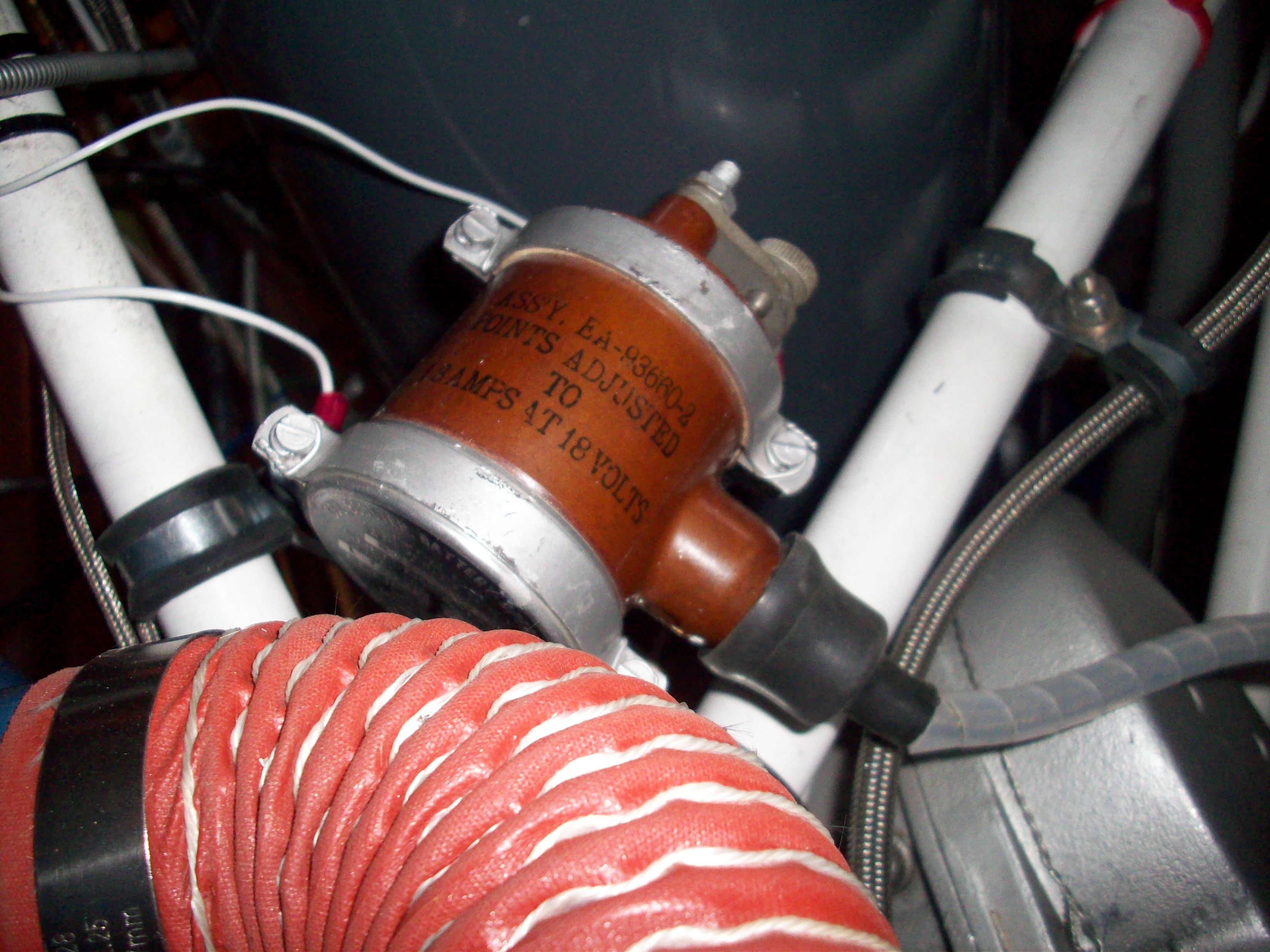
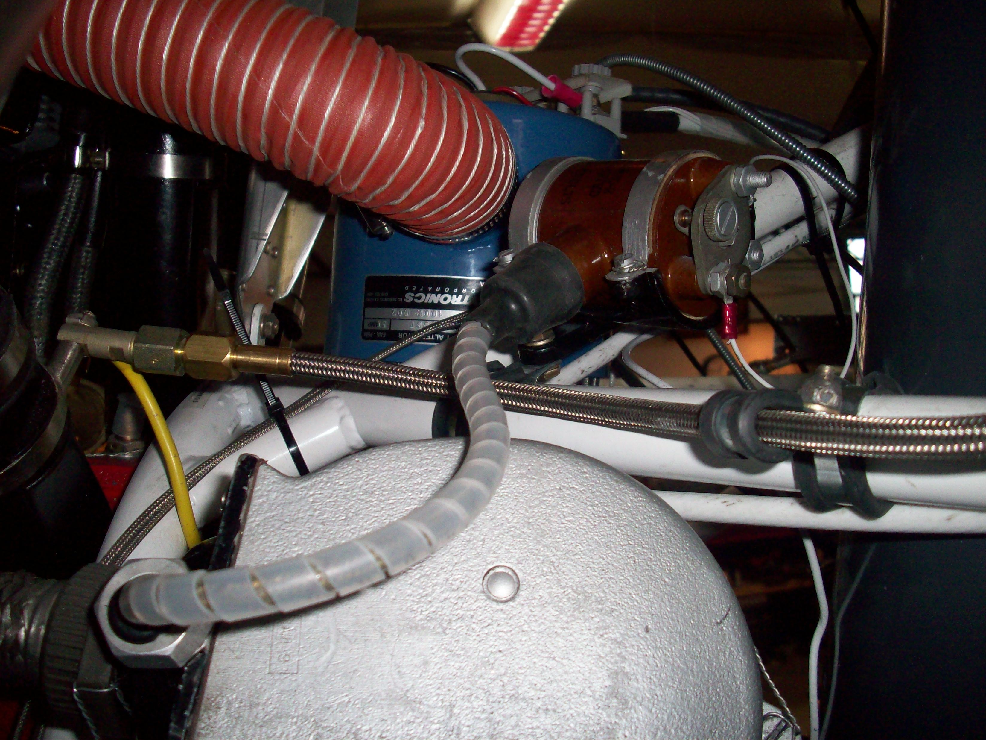
This is the booster coil I have , I have one wire + 12 on the double nutted nut. The ground wire neg is on the chassis because I have it mounted with Adel clamps. Is this correct? I Have it wired to start with "mags off". The boost coil operates ONLY when the start button, air or electric, is depressed. After the engine starts I turn on the mags.
Cheers Henry Moose 294
| | - The Matronics M14PEngines-List Email Forum - | | | Use the List Feature Navigator to browse the many List utilities available such as the Email Subscriptions page, Archive Search & Download, 7-Day Browse, Chat, FAQ, Photoshare, and much more:
http://www.matronics.com/Navigator?M14PEngines-List |
|
| Description: |
|
| Filesize: |
884.04 KB |
| Viewed: |
19506 Time(s) |
|
| Description: |
|
| Filesize: |
926 KB |
| Viewed: |
19506 Time(s) |
|
_________________
Currently building a Murphy Moose - any help would be appreciated. |
|
| Back to top |
|
|
mark.bitterlich(at)navy.m
Guest
|
| Posted: Tue Jan 05, 2010 11:56 am Post subject: Booster coil |
|
|
That is incorrect... Assuming it is a standard Russian or Chineese

booster coil.  If you are using something else, please let me know ok?


First, it is a 24 volt unit, not a 12 volt unit.  It MIGHT work at 12

volts but will never have the correct output.


The ground goes on the double nut, not the positive voltage.


You've got it backwards.


Putting the ground wire neg on the chassis will not work.


Please go back and read what I sent you before.


With it hooked up as you have stated, it simply will not work... But

since you do not have a complete circuit, you won't blow anything up.


 "The boost coil operates ONLY when the start button, air or electric,

is depressed. After the engine starts I turn on the mags."


That is correct.


To repeat:


To attach the actual power leads (as Dennis said: 24 vdc) to the coil,

you need to split the case of the boost coil in half.  (remove the 4

screws on the side after un- bending the locking tabs).


Inside you will see a terminal right next to a black knurled knob that

is used to adjust the point gap on the buzzer that makes the thing work

to begin with.  That is your GROUND connection. IT ALSO HAD A DOUBLE NUT

ON IT!!!   As you are looking at the thing face on, with that terminal

facing you, you will see the black adjustment knob on the left, then

going clockwise you will see the double-nutted terminal that is the

GROUND.


Going further clockwise you will see a terminal that is stand alone.  It

is hooked to nothing else electrically.  All by itself.  That is the

main 28 vdc power input connection.  Going further around (about 5

o'clock now) you will see a nut that connects to the buzzer leaf spring)

.  Leave that alone.


The unit does not get it's ground from the case.


--
| | - The Matronics M14PEngines-List Email Forum - | | | Use the List Feature Navigator to browse the many List utilities available such as the Email Subscriptions page, Archive Search & Download, 7-Day Browse, Chat, FAQ, Photoshare, and much more:
http://www.matronics.com/Navigator?M14PEngines-List |
|
|
|
| Back to top |
|
|
mark.bitterlich(at)navy.m
Guest
|
| Posted: Tue Jan 05, 2010 11:56 am Post subject: Booster coil |
|
|
I think you have it now.  Make sure when you have it all done and you go

to remove the "knurled knob" that you hold the part that the shield gets

soldered to still as you rotate the threaded knurled knob, or you will

end up twisting the shield right off.  Happens all the time to many

owners and this is where they end up getting all that radio noise from!

Next, from memory (it's been about 5 years), I think that the center

wire.. The actual P lead itself, gets SOLDERED to something as well and

then you screw that tire cap looking thing over the end of it.  I am

pretty sure EVERYTHING gets soldered.  I can take on apart tonight and

look if you would like.


On the shield, no you have that wrong.


When you grab the threaded knurled knob, you will see that as you hold

it in your hand, there is ANOTHER piece that it slides OVER.  That piece

looks like a little FUNNEL, where the top of the funnel comes out the

BACK of the threaded knurled knob.  You push the whole wire THROUGH that

center piece, push the shield back and solder it to the INSIDE of that

funnel piece.  You do NOT just take the shield and wrap it around

anything.


You need a picture!  And that is not an insult... It is very hard to

describe this thing.


Mark


--
| | - The Matronics M14PEngines-List Email Forum - | | | Use the List Feature Navigator to browse the many List utilities available such as the Email Subscriptions page, Archive Search & Download, 7-Day Browse, Chat, FAQ, Photoshare, and much more:
http://www.matronics.com/Navigator?M14PEngines-List |
|
|
|
| Back to top |
|
|
|
|
You cannot post new topics in this forum
You cannot reply to topics in this forum
You cannot edit your posts in this forum
You cannot delete your posts in this forum
You cannot vote in polls in this forum
You cannot attach files in this forum
You can download files in this forum
|
Powered by phpBB © 2001, 2005 phpBB Group
|

