 |
Matronics Email Lists
Web Forum Interface to the Matronics Email Lists
|
| View previous topic :: View next topic |
| Author |
Message |
nuckolls.bob(at)aeroelect
Guest
|
 Posted: Wed Jan 24, 2024 10:08 am Post subject: OVM-14 MkIII development (update) Posted: Wed Jan 24, 2024 10:08 am Post subject: OVM-14 MkIII development (update) |
 |
|
Haven't been ignoring you guys . . . fun projects got
kinda diluted with holiday festivities and frivolities
along with a few home maintenance items that could
not wait . . .
But in the mean time:
I've been fiddling with the etched circuit for the
prototype OVM-14 upgrade . . . due to the very compact
ecb layout I was interested in exploring solder reflow
assembly processes using joint-by-joint application
of solder paste.
The experiments were frustrating. The consistency
and makeup of the solder 'paste' is critical. Samples
I had on hand proved problematic in that they were
reluctant to 'stick' to the pad until the component
was placed. Seems this stuff has a shelf life too.
Finally did conquer the process but while working
with these cute little boards, it occurred to me
that it was a bit late in my career life cycle
to be spooling up in new manufacturing processes and
inventorying new products!
To my way of thinking, the optimized assembly
configuration would lend itself to offering
bare boards or even kits in addition to limited
sales of completed assemblies while striving
for compact assembly.
Thought I give this a try:
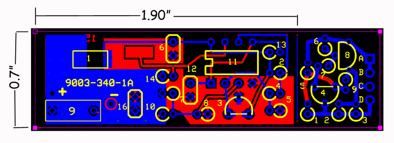
The attached figure is a snapshot of the present
configuration OVM-14 ECB. It's not terribly
larger than the legacy CBOVMs. I've not used
this assembly technique in more years than I
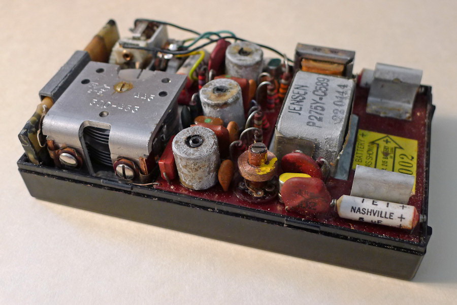
can recall . . . first observed it in the
fabrication of my first solid state pocket
radio. A Regency TR1 that cost me a pretty
penny in newspaper route earnings about 1958!
Note the resistors stand on end soldered into
pads with very close spacing. This offers
a tighter layout opportunity with another
benefit: The upper end of each resistor can
be oriented such that it attaches to an
interesting 'test node' on the board. An
oscilloscope or voltmeter probe can be clipped
to the lead wire for performance evaluation
and/or troubleshooting.
What, you may ask, is that 'thing' hanging
off the end of the board? My short path
to low cost prototype boards is predicated
on a fixed 3.8 x 2.5 inch coupon. Hmmm . . .
what to do with that opportunity for a 'free'
ecb?
How about exploring a recently noticed LED
product that caters to night time drone
pilots? Red or green LEDs with built in
flashers. A bit slower than I'd like but
certainly bright enough. I've added a little
'parasite' board to the layout to proof an
idea for a precision low volts warning
annunciator with a very low parts count.
I'll publish drawings for the ECB
shortly with the notion of exploiting
any willing talents for proofing the
layout. I've got an order into Digikey
for thru-hole parts to assemble the prototypes
which should go VERY quickly.
This may not be the optimal route but I
think it's better than the rabbit hole
I dove into the first time. Let's see
what shakes out.
Bob . . .
////
(o o)
===========o00o=(_)=o00o=========
< Go ahead, make my day . . . >
< show me where I'm wrong. >
=================================
In the interest of creative evolution
of the-best-we-know-how-to-do based
on physics and good practice.
| | - The Matronics AeroElectric-List Email Forum - | | | Use the List Feature Navigator to browse the many List utilities available such as the Email Subscriptions page, Archive Search & Download, 7-Day Browse, Chat, FAQ, Photoshare, and much more:
http://www.matronics.com/Navigator?AeroElectric-List |
|
| Description: |
|
| Filesize: |
222.1 KB |
| Viewed: |
5713487 Time(s) |
|
| Description: |
|
| Filesize: |
142.91 KB |
| Viewed: |
5713484 Time(s) |
|
|
|
| Back to top |
|
 |
merlewagner2
Joined: 01 Jun 2016
Posts: 18
Location: Spring Hill, FL
|
| Posted: Thu Jan 25, 2024 3:57 am Post subject: Re: OVM-14 MkIII development (update) |
|
|
Bob,
If you send me the schematic I can then make up a board with SMD and have it made by PCBway. They are very cost effective.
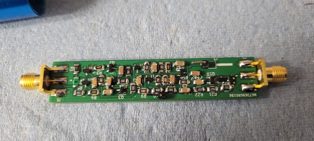
As an example the photo is an RF/audio probe I just finished using SMD. I used 1206 sized SMD for this.
| | - The Matronics AeroElectric-List Email Forum - | | | Use the List Feature Navigator to browse the many List utilities available such as the Email Subscriptions page, Archive Search & Download, 7-Day Browse, Chat, FAQ, Photoshare, and much more:
http://www.matronics.com/Navigator?AeroElectric-List |
|
| Description: |
|
| Filesize: |
415.29 KB |
| Viewed: |
5713465 Time(s) |
|
_________________
KC1DNJ
General Radiotelephone
Commercial SEL
A & P
Building scale P51, rebuilding Tailwind W10 |
|
| Back to top |
|
|
nuckolls.bob(at)aeroelect
Guest
|
| Posted: Mon Jan 29, 2024 9:56 am Post subject: OVM-14 MkIII development (update) |
|
|
At 05:57 AM 1/25/2024, you wrote:
| Quote: | --> AeroElectric-List message posted by: "merlewagner2" <wagnermerle(at)gmail.com>
Bob,
If you send me the schematic I can then make up a board with SMD and have it made by PCBway. They are very cost effective.
As an example the photo is an RF/audio probe I just finished using SMD. I used 1206 sized SMD for this. |
Thank you so much for the offer sir. BTW, nice
looking assembly. SMA connectors? What does it do?
I did a surface mount ECB and already have the
boards. However, while resolving some issues with
solder paste dispensing I had an epiphany . . .
I'm not at the stage of my 'career' to be
launching a project to be manufactured in
my shops.
Decided to convert it to thru-hole so that
I might offer kits . . . and perhaps get
some local kids interested in learning how
to put such things together. I've published
the 'plan-b' details in another posting. I'll
comb it for errors one more time and get
boards on order. Should be here Friday.
I'll also get an order in to Digikey for
parts compliment.
If you'd care to proof the layout yourself,
your input would be truly appreciated.
It's a bit risky to proof one's personal
work product . . . but then I'm probably
not telling you anything you don't already
know!
Yeah, about that 1206 footprint . . . that's
been my favorite choice for hand assembly for
the past 20 years or so!
Bob . . .
////
(o o)
===========o00o=(_)=o00o=========
< Go ahead, make my day . . . >
< show me where I'm wrong. >
=================================
In the interest of creative evolution
of the-best-we-know-how-to-do based
on physics and good practice.
| | - The Matronics AeroElectric-List Email Forum - | | | Use the List Feature Navigator to browse the many List utilities available such as the Email Subscriptions page, Archive Search & Download, 7-Day Browse, Chat, FAQ, Photoshare, and much more:
http://www.matronics.com/Navigator?AeroElectric-List |
|
|
|
| Back to top |
|
|
nuckolls.bob(at)aeroelect
Guest
|
| Posted: Mon Jan 29, 2024 10:02 am Post subject: OVM-14 MkIII development (update) |
|
|
I've published the ECB layout and assy data at


  https://tinyurl.com/ytdg9ehf


 Any any assistance in proofing the layout to the

 schematic would be appreciated. Will order boards

 late tonight.


 Got an order about ready to ship to Digikey for

 parts.


 We might get this project into smoke-test yet!


   Bob . . .


                    ////

                   (o o)

    ===========o00o=(_)=o00o=========

    < Go ahead, make my day . . .   >

    < show me where I'm wrong.      >

    =================================


    In the interest of creative evolution

    of the-best-we-know-how-to-do based

    on physics and good practice.
| | - The Matronics AeroElectric-List Email Forum - | | | Use the List Feature Navigator to browse the many List utilities available such as the Email Subscriptions page, Archive Search & Download, 7-Day Browse, Chat, FAQ, Photoshare, and much more:
http://www.matronics.com/Navigator?AeroElectric-List |
|
|
|
| Back to top |
|
|
pjc
Joined: 13 Jan 2021
Posts: 7
|
| Posted: Mon Jan 29, 2024 11:04 am Post subject: OVM-14 MkIII development (update) |
|
|
Bob,
Still interested in being a beta-tester. With the through-hole redesign I can probably competently assemble it myself! Even better for my use case if the low voltage warning light/LED option is included.
Peter
| Quote: | On Jan 29, 2024, at 10:12â¯AM, Robert L. Nuckolls, III <nuckolls.bob(at)aeroelectric.com> wrote:
 I've published the ECB layout and assy data at
https://tinyurl.com/ytdg9ehf
Any any assistance in proofing the layout to the
schematic would be appreciated. Will order boards
late tonight.
Got an order about ready to ship to Digikey for
parts.
We might get this project into smoke-test yet!
Bob . . .
////
(o o)
===========o00o=(_)=o00o=========
< Go ahead, make my day . . . >
< show me where I'm wrong. >
=================================
In the interest of creative evolution
of the-best-we-know-how-to-do based
on physics and good practice.
|
| | - The Matronics AeroElectric-List Email Forum - | | | Use the List Feature Navigator to browse the many List utilities available such as the Email Subscriptions page, Archive Search & Download, 7-Day Browse, Chat, FAQ, Photoshare, and much more:
http://www.matronics.com/Navigator?AeroElectric-List |
|
|
|
| Back to top |
|
|
nuckolls.bob(at)aeroelect
Guest
|
| Posted: Mon Jan 29, 2024 12:01 pm Post subject: OVM-14 MkIII development (update) |
|
|
At 01:03 PM 1/29/2024, you wrote:
| Quote: | Bob,
Still interested in being a beta-tester. With the through-hole redesign I can probably competently assemble it myself! Even better for my use case if the low voltage warning light/LED option is included.
Peter
|
You're at the top of the list. We'll assemble the
first 'batch' here for testing. The lv warning
board gets trimmed off . . . that's a separate
project that's still under cultivation. But you
can have one of those too once they're ready
for prime time.
Bob . . .
////
(o o)
===========o00o=(_)=o00o=========
< Go ahead, make my day . . . >
< show me where I'm wrong. >
=================================
In the interest of creative evolution
of the-best-we-know-how-to-do based
on physics and good practice.
| | - The Matronics AeroElectric-List Email Forum - | | | Use the List Feature Navigator to browse the many List utilities available such as the Email Subscriptions page, Archive Search & Download, 7-Day Browse, Chat, FAQ, Photoshare, and much more:
http://www.matronics.com/Navigator?AeroElectric-List |
|
|
|
| Back to top |
|
|
merlewagner2
Joined: 01 Jun 2016
Posts: 18
Location: Spring Hill, FL
|
| Posted: Mon Jan 29, 2024 1:16 pm Post subject: Re: OVM-14 MkIII development (update) |
|
|
[quote="nuckolls.bob(at)aeroelect"]At 05:57 AM 1/25/2024, you wrote:

 [quote]--> AeroElectric-List message posted by: "merlewagner2" <wagnermerle>


   Thank you so much for the offer sir. BTW, nice

   looking assembly.  SMA connectors? What does it do?


 /quote]


Bob, The unit displayed is an RF/audio probe for signal tracing. this feeds an amplifier. Yes, SMA connectors. It makes a nice compact unit using RG 174 as a lead. The probe is powered from the amp.


I am not sure how this is going to get displayed as I rarely use quotes or even reply.


Merle
| | - The Matronics AeroElectric-List Email Forum - | | | Use the List Feature Navigator to browse the many List utilities available such as the Email Subscriptions page, Archive Search & Download, 7-Day Browse, Chat, FAQ, Photoshare, and much more:
http://www.matronics.com/Navigator?AeroElectric-List |
|
_________________
KC1DNJ
General Radiotelephone
Commercial SEL
A & P
Building scale P51, rebuilding Tailwind W10 |
|
| Back to top |
|
|
merlewagner2
Joined: 01 Jun 2016
Posts: 18
Location: Spring Hill, FL
|
| Posted: Tue Jan 30, 2024 7:02 am Post subject: Re: OVM-14 MkIII development (update) |
|
|
| nuckolls.bob(at)aeroelect wrote: | I've published the ECB layout and assy data at
https://tinyurl.com/ytdg9ehf
Any any assistance in proofing the layout to the
schematic would be appreciated. Will order boards
late tonight.
Got an order about ready to ship to Digikey for
parts.
We might get this project into smoke-test yet!
Bob . . .
|
I looked at your layout and after finally figuring out the semantics it looks OK initially. It was confusing until I understood the numbering scheme for components.
For me it usually takes about 3 iterations to figure out what I forgot. At 82 I am finally recognizing a memory failure.
Merle
| | - The Matronics AeroElectric-List Email Forum - | | | Use the List Feature Navigator to browse the many List utilities available such as the Email Subscriptions page, Archive Search & Download, 7-Day Browse, Chat, FAQ, Photoshare, and much more:
http://www.matronics.com/Navigator?AeroElectric-List |
|
_________________
KC1DNJ
General Radiotelephone
Commercial SEL
A & P
Building scale P51, rebuilding Tailwind W10 |
|
| Back to top |
|
|
nuckolls.bob(at)aeroelect
Guest
|
| Posted: Fri Feb 09, 2024 8:55 am Post subject: OVM-14 MkIII development (update) |
|
|
Boards are on order . . . stared at that last

 iteration of the layout and finally succumbed

 to an instance of 'creative destruction'. I've

 re-laid the board to more conventional fabrication

 philosophies. Yeah, it got a bit bigger but will

 go together in minutes and 'look good'.


 The assembly is now 2.2 x 0.7 inches and will

 still 'house' nicely under a piece of heat

 shrink.


 Those interested in taking a peek can download

 the proof prints at:


  http://aeroelectric.com/DIY/OVM14%20mkII%20proof%20prints.pdf


 The boards will be solder masked and silk screened

 to facilitate kit-builders. Parts and boards will be

 on hand for 15 prototypes next Thursday.


   Bob . . .


                    ////

                   (o o)

    ===========o00o=(_)=o00o=========

    < Go ahead, make my day . . .   >

    < show me where I'm wrong.      >

    =================================


    In the interest of creative evolution

    of the-best-we-know-how-to-do based

    on physics and good practice.
| | - The Matronics AeroElectric-List Email Forum - | | | Use the List Feature Navigator to browse the many List utilities available such as the Email Subscriptions page, Archive Search & Download, 7-Day Browse, Chat, FAQ, Photoshare, and much more:
http://www.matronics.com/Navigator?AeroElectric-List |
|
|
|
| Back to top |
|
|
1rv4
Joined: 11 Sep 2006
Posts: 25
|
| Posted: Fri Feb 09, 2024 5:15 pm Post subject: OVM-14 MkIII development (update) |
|
|
Hi BobVery interested in a kit or a completed and tested one.
 Thanks
  Chris
On Fri., Feb. 9, 2024, 9:10 a.m. Robert L. Nuckolls, III, <nuckolls.bob(at)aeroelectric.com (nuckolls.bob(at)aeroelectric.com)> wrote:
| Quote: | Boards are on order . . . stared at that last
iteration of the layout and finally succumbed
to an instance of 'creative destruction'. I've
re-laid the board to more conventional fabrication
philosophies. Yeah, it got a bit bigger but will
go together in minutes and 'look good'.
The assembly is now 2.2 x 0.7 inches and will
still 'house' nicely under a piece of heat
shrink.
Those interested in taking a peek can download
the proof prints at:
http://aeroelectric.com/DIY/OVM14%20mkII%20proof%20prints.pdf
The boards will be solder masked and silk screened
to facilitate kit-builders. Parts and boards will be
on hand for 15 prototypes next Thursday.
 Bob . . .
                  ////
                 (o o)
  ===========o00o=(_)=o00o=========
  < Go ahead, make my day . . .  >
  < show me where I'm wrong.     >
  =================================
Â
  In the interest of creative evolution
  of the-best-we-know-how-to-do based
  on physics and good practice.
|
| | - The Matronics AeroElectric-List Email Forum - | | | Use the List Feature Navigator to browse the many List utilities available such as the Email Subscriptions page, Archive Search & Download, 7-Day Browse, Chat, FAQ, Photoshare, and much more:
http://www.matronics.com/Navigator?AeroElectric-List |
|
|
|
| Back to top |
|
|
pjc
Joined: 13 Jan 2021
Posts: 7
|
| Posted: Wed May 29, 2024 9:52 pm Post subject: Re: OVM-14 MkIII development (update) |
|
|
Bob (or others),
Iâve not been keeping up with the mailing list lately, and at some point there seemed to be a service outage, so apologies if I should know better., but â¦
Has there been any further progress on the ânewâ OVM module?
PJC
| | - The Matronics AeroElectric-List Email Forum - | | | Use the List Feature Navigator to browse the many List utilities available such as the Email Subscriptions page, Archive Search & Download, 7-Day Browse, Chat, FAQ, Photoshare, and much more:
http://www.matronics.com/Navigator?AeroElectric-List |
|
|
|
| Back to top |
|
|
Eric Page
Joined: 15 Feb 2017
Posts: 278
|
| Posted: Mon Apr 07, 2025 6:32 pm Post subject: Re: OVM-14 MkIII development (update) |
|
|
There haven't been any updates on Bob's OVM-14 Mk III overvoltage protection module since Feb 2024 so I took a look at it to see what I could do.  I found some minor things that might have been problems, so I made a few small changes:


1. Looking at the datasheet for the crowbar SCR... [https://tinyurl.com/yjvrdtfx] ...the specification for gate triggering current states that it could take as much as 15mA to trigger.  As configured in the last schematic that Bob posted... [https://tinyurl.com/3jeddsky] ...with the gate drive resistor (R14) of 2.49k ohms connected to the bus, 15mA gate current would not be achieved until the overvoltage exceeded 37V.


CHANGE: R14 reduced to 620 ohms and connected to the 10V supply rail instead of the bus.  This provides 16mA to trigger the SCR's gate, while preventing an overcurrent through the output of comparator U11.B (maximum 20mA).


2. At a bus voltage of 14V, current-limiting resistor R1 (392 ohms) would dissipate of about 1/3 watt, and would run hot.


CHANGE: R1 increased to 470 ohms and pass transistor Q17 added.  This provides a sturdy 10V supply rail for the circuit, including adequate gate current to trigger the SCR.  Continuous power dissipation in R1 will be reduced to 0.03W.  At the high end of its 1% tolerance (475 ohms), with bus voltage at 12V, R1 will provide 3mA to U3 and the base of Q17, more than double the minimum required for regulation.  At the low end of its tolerance (465 ohms), R1 will protect U3 against exceeding its absolute maximum current rating up to a ridiculous bus voltage of 81V.


3. The trip delay capacitor (C12) is a ceramic type, which may not be stable in a timing application due to the effects of DC bias, temperature and aging.


CHANGE: C12 changed to a 5% tolerance solid tantalum type.


-----


With that done, I created a board layout that's very similar to Bob's and is the same size (0.7" x 2.2").  It still uses all through-hole parts except the SCR, which is large for a surface mount component and is relatively easy to hand solder.  I moved the SCR to the top side of the board and added a 2-position 0.25" quick-connect terminal to make installation easy (wires can still be soldered directly to the board if preferred).  I also changed to a "piano key" style DIP switch to activate the maintenance mode, which makes the switch accessible at the end of the assembly after heat shrink is applied.


After building a prototype, I found that the resistors that set the trip voltages didn't quite work as calculated, so I tweaked them experimentally to find the values that provide a normal trip at 16.0V (R8 = 2.61k) and a maintenance test mode trip at 13.7V (R10 = 69.8k).  To ensure that maintenance test mode works correctly with all battery types, I bumped the test mode trip point up by 0.2V, from 13.5V to 13.7V.  This will accommodate the higher resting voltage of a fully charged LiFePO4 battery (typically 3.4V per cell, or 13.6V for a 4-cell battery).


Finally, I assembled four additional prototypes and tested all five.  In each case, the modules tripped at the desired voltage and in the desired time, blowing a 5 amp fuse with no discernable heating of the SCR.


Full documentation for the project is attached to this post.  You'll find links on page 7 to purchase circuit boards and components.
| | - The Matronics AeroElectric-List Email Forum - | | | Use the List Feature Navigator to browse the many List utilities available such as the Email Subscriptions page, Archive Search & Download, 7-Day Browse, Chat, FAQ, Photoshare, and much more:
http://www.matronics.com/Navigator?AeroElectric-List |
|
| Description: |
|

Download |
| Filename: |
Nuckolls OVM-14 MkIII (Rev 1d).pdf |
| Filesize: |
610.59 KB |
| Downloaded: |
30370 Time(s) |
|
|
| Back to top |
|
|
user9253
Joined: 28 Mar 2008
Posts: 1975
Location: Riley TWP Michigan
|
| Posted: Tue Apr 08, 2025 5:02 am Post subject: Re: OVM-14 MkIII development (update) |
|
|
Wow Eric, you went to a lot of work to help out aircraft owners and builders.

Your excellent documentation will allow even a complete novice to build an

overvoltage protection circuit.  I like the through hole design.  Expert soldering

skills are not required.  I commend your efforts to help others.
| | - The Matronics AeroElectric-List Email Forum - | | | Use the List Feature Navigator to browse the many List utilities available such as the Email Subscriptions page, Archive Search & Download, 7-Day Browse, Chat, FAQ, Photoshare, and much more:
http://www.matronics.com/Navigator?AeroElectric-List |
|
_________________
Joe Gores |
|
| Back to top |
|
|
dj_theis
Joined: 28 Aug 2017
Posts: 68
Location: Minnesota
|
| Posted: Tue Apr 08, 2025 6:12 am Post subject: Re: OVM-14 MkIII development (update) |
|
|
Very nice.
I second Joeâs recognition of your contribution to the group, Eric.
Dan T.
| | - The Matronics AeroElectric-List Email Forum - | | | Use the List Feature Navigator to browse the many List utilities available such as the Email Subscriptions page, Archive Search & Download, 7-Day Browse, Chat, FAQ, Photoshare, and much more:
http://www.matronics.com/Navigator?AeroElectric-List |
|
_________________
Dan Theis
Scratch building Sonex #1362
Revmaster Alternator problem solved. |
|
| Back to top |
|
|
|
|
You cannot post new topics in this forum
You cannot reply to topics in this forum
You cannot edit your posts in this forum
You cannot delete your posts in this forum
You cannot vote in polls in this forum
You cannot attach files in this forum
You can download files in this forum
|
Powered by phpBB © 2001, 2005 phpBB Group
|

