finn.lassen(at)verizon.ne
Guest
|
 Posted: Mon Sep 25, 2023 11:40 am Post subject: Hall as current sensors Posted: Mon Sep 25, 2023 11:40 am Post subject: Hall as current sensors |
 |
|
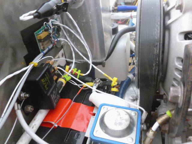
After reading the Hall of fame       article by Jim Weir in the July 2019 Kitplanes magazine I       purchased the T50-26 ferrite toroids and drv5053VA Hall effect       sensors and put the notched toroids on cables to/from battery       before I crimped and soldered the terminals.


       This month I finally got around to making the sensors and an       amplifier board for then (going to analog inputs of an Arduino       Mega 2590 with data logging on SDRAM card and 4x20 character       display). Attached my schematic of amplifiers. (Not           shown the hall sensors with 22nF across power and ground fed           by the Mega 2590's 5V power output.)


           Datasheet https://www.ti.com/lit/ds/symlink/drv5053.pdf shows           that the zero current output from them can vary between 0.9V           to 1.15V, thus the need for the potentiometers for zero           adjustment. The max output range is 0.81V before saturation           with typical -90mV/mTesla and saturation of 9mT.


           On the bench with about 10 amps thru the toroids I got from 12           to 19 mV per amp with the four different sensors in the           toroids.


           Note that the LM324 opamps max output is supply - 1.5V (3.5V           in my case).


       I wanted four sensors: Engine bus, Main bus, Alternator output and       Starter. However, looking at the datasheet for the drv5053VA       sensor it was obvious it would be overloaded (saturated) at       starter currents, so I decided to use the forth sensor for       Alternator field current.


       I wanted about 20A max range for Engine and Main buses, 40 - 50       amps (hall sensor saturation) for alternator output and about 7 to       10 amps for alternator field. Using resistors I had on hand I       arrived at these amplification factors:

       Engine bus: 7.5x

       Main bus: 6.8x

       Alternator out: 4.7x

       Alternator field: 33x


       In theory this should all have worked fine. Install the sensors       and amplifier board, zero out each amplifier with no currents       running. Then run about 10 to 12 amps (1 ohm 120W resistor) with       a� 0.020 ohm 1% resistor in series and measure voltage across that       to get actual current (didn't know tolerance of 1 ohm resistor).       Compare voltage with displayed voltage on Arduino display and       program correction factors for each of the four channels       (sensors).


       Worked fine with the Alternator field current sensor (installed       further from other sensors).


       However, when I turned on current to alternator field (engine not       running) the engine bus and alternator out current displays jumped       from zero!


       Penny finally dropped that the alternator magnetic field is way       too close to the current sensors as installed. I should have       realized that when I had trouble adjusting the Alternator out to       zero (that sensor is mounted just a few inches from the       alternator).


       So that is the purpose of this thread: to warn anybody that might       use this method to measure currents that the sensors are sensitive       to surrounding magnetic fields, permanent and varying (like the       alternator field).


       Obvious solution would be to move the sensors to locations further       from magnetic fields. But in my case that would require removing       and reinstalling crimped and soldered ring terminals on the       cables. And for the Alternator out I would have to add a       significant length of wire between alternator and the battery to       get that sensor away from the alternator. So much for my elegant       short wire between alternator and battery


       Perhaps a better solution in my case (at least for the engine and       main bus) is to measure the voltages over the 3 - 4 feet long       10AWG cables from battery to fuse panels using the opamps as       differential amps. 10V zeners from each end of cables to inverting       and non-inverting inputs respectively. Still need to figure out       exact schematic and values.


       But, again, beware using Hall effect current sensors near external       magnetic fields.


       Finn
| | - The Matronics AeroElectric-List Email Forum - | | | Use the List Feature Navigator to browse the many List utilities available such as the Email Subscriptions page, Archive Search & Download, 7-Day Browse, Chat, FAQ, Photoshare, and much more:
http://www.matronics.com/Navigator?AeroElectric-List |
|
| Description: |
|
| Filesize: |
78.6 KB |
| Viewed: |
609 Time(s) |
|
| Description: |
|

Download |
| Filename: |
CurrentSensors.pdf |
| Filesize: |
10.85 KB |
| Downloaded: |
33 Time(s) |
|
|

