 |
Matronics Email Lists
Web Forum Interface to the Matronics Email Lists
|
| View previous topic :: View next topic |
| Author |
Message |
nuckolls.bob(at)aeroelect
Guest
|
 Posted: Mon Sep 26, 2022 11:49 am Post subject: AC current reading for Revmaster engine Posted: Mon Sep 26, 2022 11:49 am Post subject: AC current reading for Revmaster engine |
 |
|
At 08:22 AM 9/25/2022, you wrote:
| Quote: | I will be monitoring the temps of the stator coils
and the voltage regulator. The voltage regulator I
will use will be the "John Deere type which I've
been told is the switching type. |
SERIES switching might be a more descriptive
term to distinguish it from the overwhelming
predominance of SWITCHING regulators that manage
energy in high frequency inductors/transformers.
| Quote: | I have been told by Revmaster that their regulator is the shunt type.
Unfortunately there seems to be no way of knowing for sure beforehand
what type of regulator a specific unit is. That information is
not included in any descriptions. |
I'm not sure that the voltage control philosophy
is terribly germane to your investigation. The
Revmaster community has predominately held that
alternator failures are closely associated with
loading of the alternator at or near maximum
output. This idea reinforced by suggestions
that batteries will particularly low internal
resistance are especially deleterious to
alternator service life.
When an alternator is heavily loaded
the shunting currents imposed by the regulator
are at a minimum. I.e. when heavily loaded,
stresses on the alternator are not
particularly driven by configuration of
regulator.
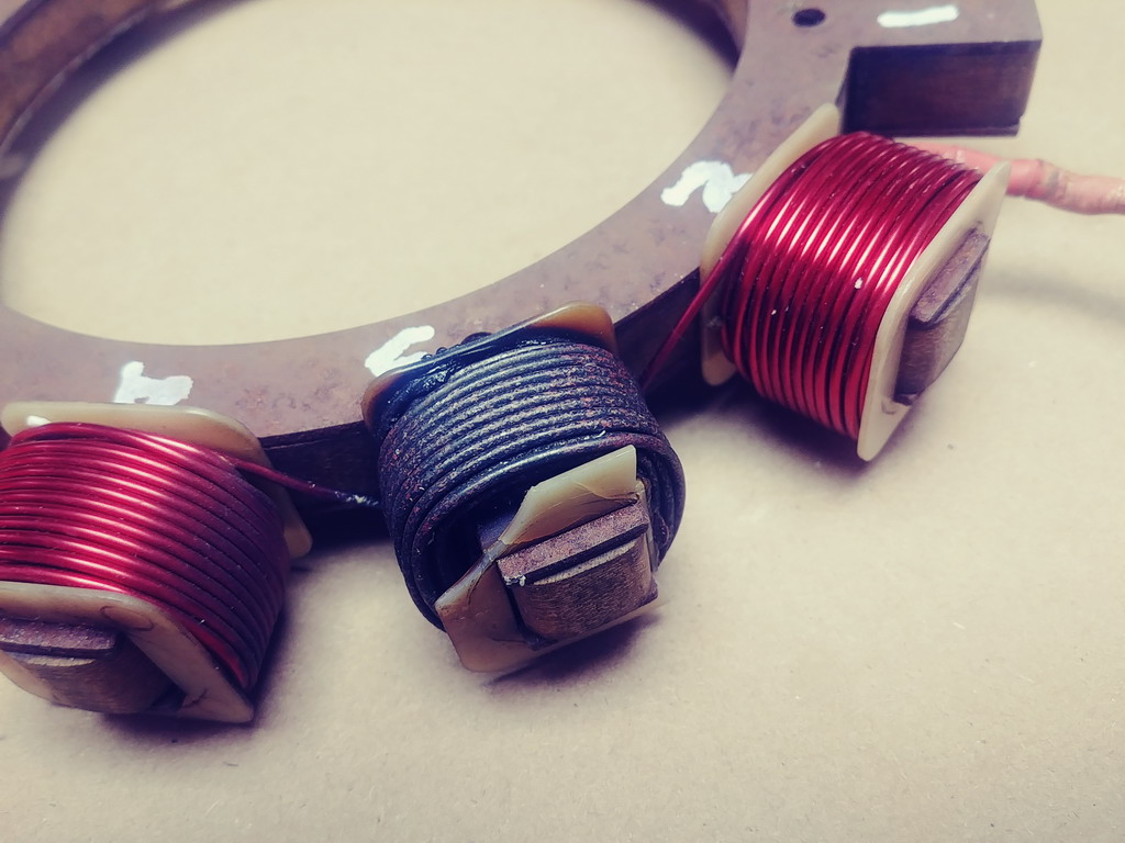
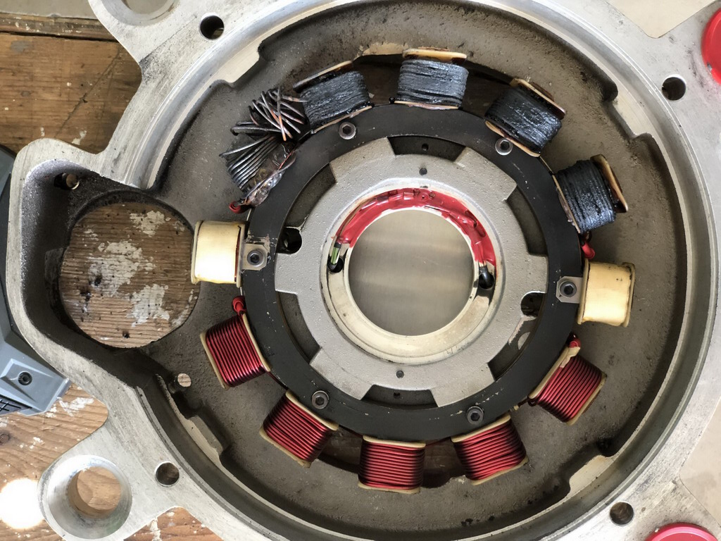
Another noteworthy feature of the failures I've
observed concerns the CONCENTRATION of overstress.
I've never personally encountered failed stator
on a rotating machine that did not present
uniform evidence of destruction over all
stator poles carrying that path of copper. We
see one such example in attached photo.
Some Revmaster alternators have tossed in the towel
after having toasted only one pole winding leaving
pristine poles on either side. But even the
illustration of total winding failure shows
one pole with much more damage than the rest.
I've seen assertions on the 'net describing
any combination of failures from single
pole to all poles.
It would be a real challenge to duplicate
a condition that replicates such a failure.
I'm reasonably certain that NO stress OUTSIDE
the alternator could produce such damage. Hence,
root cause is likely confined to INSIDE the
alternator.
Another curiosity arises with consideration
of the Revmaster PM alternator architecture.
The stator is wound with TWO separate windings
each of which drives a rectifier/regulator.
Either of the two windings is demonstrably
at risk for what seems to be an 'overload'
condition the magnitude of which is not numerically
defined but presumably considerably greater than
the factory's alternator power output ratings.
The Revmaster community has been thrashing about
looking for mitigation of failure while being
offered no methodology for quantifying and
guarding against such failures. Paul and Dan
are graciously volunteering to investigate the
cause/effect features and put numbers to them.
There have to be millions of exemplar alternator/
regulator/battery systems in everything from
mopeds to rather sophisticated heavier than
air machines. The physics for crafting such
systems having useful/satisfactory service life
is well understood.
Given my limited access to design decisions
and the totality of service history, I'm kinda
throwing darts here. But it seems that the
root cause for these failures is most likely
found in the MAGNETICS of the design as opposed
to any combination of electrics or environs. It
would be interesting to study the practicality
of fitting this engine with ONE alternator winding
of heavier wire spread over all stator poles
as opposed to TWO windings with demonstrably
fragile properties.
BTW . . . I've searched my library for a copy
of the R-2300 installation manual and came up
empty. Can anyone point me to a download link
or email me a copy?
| Quote: | | This charge system has (at least) 4 flaws. 1) low air flow/cooling. 2) erroneous stator design with magnetically saturated laminates. 3) no resin coating infusion on the windings |
Not sure that impregnation/coating of windings would
be terribly significant. This is a labor intensive
rare process in this arena. The net benefit would
be to spread heating effects more uniformly through
the winding mass but would not contribute to improved
cooling. At E-M our varnish impregnated windings were
treated mostly for improved resistance to moisture
and vibration than for thermal management.
| Quote: | 4) low air flow/cooling.
I injected DC current from a lab supply through the stator winding on the bench and measured the rise in temperature of the surface of the stator wire and the center laminate steel. I've concluded that continuous DC at 15 amps with an ambient temperature of 100 F will not create a temperature rise that is damaging (steady state of below 140 F). |
Not surprising. Temperatures required to 'toast' magnet
wire insulation are pretty severe. Back in my Electro-Mech
days, we slung a lot of magnet wire. We never used anything
less than 'class H' insulation . . . there was little to
be saved by going any lower. Most of our windings were
vacuum impregnated with a varnish and then baked. The
varnish was rated for temperatures equal to or greater than
the wire.
Another physical effect that may contribute to this
failure is tied to the temperature coefficient of resistance
for copper. This phenomenon has been studied in great
detail and accurately know for a very long time.
https://tinyurl.com/p2sjmhtn
As an practical/observable matter
Temperature rating for insulation does is not fall-off-
the-edge-of-the-earth limit. This paper speaks
to a temperature vs. service life for various insulations
https://tinyurl.com/2e7z7wwx
Class H insulation is qualified to function at rated temperature
limits for 20,000 hours with that number falling by 1/2 for
each 10 degree C increase.
Temperatures that toast the wires in one stator pole
while leaving adjacent poles relatively untouched
have to have a profound and probably very simple
explanation.
| Quote: | | Increasing air flow is job 1, wrt cooling this stator. Impregnating the wiring is an improvement that I advocate but do not have data on it. My direct conversation with the stator wire manufacturer, and their recommendation suggests to me it would be an improvement. |
Did they quantify 'improvement'?
To quote a rather intelligent fellow of some years past:
Can you measure it? Can you express it in figures?
Can you make a model of it? If not, your theory
is apt to be based more upon imagination than upon
knowledge. === Lord Kelvin ===
| Quote: | | I can share the method of impregnating the stator wiring that I'm using with the web, but I'm reluctant to advertise this until I can verify there is no damage to the ignition coils. I've tested impregnation on the stator coils but the locally mounted ignition coil wire is different (much smaller and from an unknown supplier). |
It seems unlikely that the insulation will be any less
robust
Bob . . .
Un impeachable logic: George Carlin asked, "If black boxes
survive crashes, why don't they make the whole airplane
out of that stuff?"
| | - The Matronics AeroElectric-List Email Forum - | | | Use the List Feature Navigator to browse the many List utilities available such as the Email Subscriptions page, Archive Search & Download, 7-Day Browse, Chat, FAQ, Photoshare, and much more:
http://www.matronics.com/Navigator?AeroElectric-List |
|
| Description: |
|
| Filesize: |
162.6 KB |
| Viewed: |
1508 Time(s) |
|
| Description: |
|
| Filesize: |
266.01 KB |
| Viewed: |
1508 Time(s) |
|
|
|
| Back to top |
|
 |
dj_theis
Joined: 28 Aug 2017
Posts: 56
Location: Minnesota
|
| Posted: Tue Sep 27, 2022 6:38 pm Post subject: Re: AC current reading for Revmaster engine |
|
|
| Quote: | Quote:
Increasing air flow is job 1, wrt cooling this stator. Impregnating the wiring is an improvement that I advocate but do not have data on it. My direct conversation with the stator wire manufacturer, and their recommendation suggests to me it would be an improvement.
Did they quantify 'improvement'? |
Good point.
The conversation was a follow up of my question, "what is the temperature rating of the magnet wire being used."
His response was that the coating was "designed to be soldered without direct abrasive removal of the insluation." (i.e. the heat from soldering would remove the insulation.). From memory, his suggestion was that the wire should be coated to achieve the desired insulation temperature rating. No specific level of improvement was defined other than the implicit message that the wire was not designed to be left uncoated in this type of an application.
It's likely that leaving the wire uncoated does not guarantee failure. I would guess that many or most of the stators don't fail. I don't have statistic on the failure rate of this design.
It's evident that the unusual localized heating that we've seen (and you show in the attachment) is suggestive of a very unusual heat source.
I've been kicking this around for a while and it recently occurred to me that perhaps some of localized coil failure is a result of the single phase regulator \ rectifier (that is little more than an SCR) going through a catastrophic failure as a short. this would provide the full current from the battery to feed back through the stator, at least until one of the 30 amp fuses blow.
I don't think there is any other power source other than the battery, available to cause so much damage as we see on some of these stators. It also might explain a single coil buring up. As you've often brought up, an open wire will melt at a spot somewhere in the middle. Has anyone ran a short circuit test on a multi-coil stator like this? Would it not make some sense that one isolated coil could go through the rapid rise in resistance and burn up before the rest?
Attached is the charge circuit as I believe it is with the OEM regulator. I've added an overvoltage relay but I think we can ignore that component from the discussion.
Thoughts?
| | - The Matronics AeroElectric-List Email Forum - | | | Use the List Feature Navigator to browse the many List utilities available such as the Email Subscriptions page, Archive Search & Download, 7-Day Browse, Chat, FAQ, Photoshare, and much more:
http://www.matronics.com/Navigator?AeroElectric-List |
|
| Description: |
|

Download |
| Filename: |
Revmaster 2300 rev13 alternator ckt.pdf |
| Filesize: |
63.23 KB |
| Downloaded: |
114 Time(s) |
_________________
Dan Theis
Scratch building Sonex #1362
Still working on the Revmaster Alternator improvement |
|
| Back to top |
|
|
dj_theis
Joined: 28 Aug 2017
Posts: 56
Location: Minnesota
|
| Posted: Tue Sep 27, 2022 6:45 pm Post subject: Re: AC current reading for Revmaster engine |
|
|
| Quote: | BTW . . . I've searched my library for a copy
of the R-2300 installation manual and came up
empty. Can anyone point me to a download link
or email me a copy? |
Attached is the "Electrical" portion of the Revmaster manual.
| | - The Matronics AeroElectric-List Email Forum - | | | Use the List Feature Navigator to browse the many List utilities available such as the Email Subscriptions page, Archive Search & Download, 7-Day Browse, Chat, FAQ, Photoshare, and much more:
http://www.matronics.com/Navigator?AeroElectric-List |
|
| Description: |
|
Download |
| Filename: |
Revmatser R-2300 Manual C - CDI Electrical.pdf |
| Filesize: |
1.38 MB |
| Downloaded: |
104 Time(s) |
_________________
Dan Theis
Scratch building Sonex #1362
Still working on the Revmaster Alternator improvement |
|
| Back to top |
|
|
user9253
Joined: 28 Mar 2008
Posts: 1908
Location: Riley TWP Michigan
|
| Posted: Wed Sep 28, 2022 7:34 am Post subject: Re: AC current reading for Revmaster engine |
|
|
Dan,

Your theory about battery current destroying the dynamo coils makes sense.

If correct, then I can think of a couple of solutions.

1. Replace the 30 amp fuses with 20 amp ones.  And limit the aircraft load to 15 amps.  If the regulator shorts out, then a fuse will blow.

2. Put a Schottky diode in series with the voltage regulator output.  If the regulator shorts out, the diode will block battery current.
| | - The Matronics AeroElectric-List Email Forum - | | | Use the List Feature Navigator to browse the many List utilities available such as the Email Subscriptions page, Archive Search & Download, 7-Day Browse, Chat, FAQ, Photoshare, and much more:
http://www.matronics.com/Navigator?AeroElectric-List |
|
_________________
Joe Gores |
|
| Back to top |
|
|
nuckolls.bob(at)aeroelect
Guest
|
| Posted: Wed Sep 28, 2022 6:24 pm Post subject: AC current reading for Revmaster engine |
|
|
| Quote: | The conversation was a follow up of my question, "what is the temperature rating of the magnet wire being used."
His response was that the coating was "designed to be soldered without direct abrasive removal of the insluation." (i.e. the heat from soldering would remove the insulation.). From memory, his suggestion was that the wire should be coated to achieve the desired insulation temperature rating. No specific level of improvement was defined other than the implicit message that the wire was not designed to be left uncoated in this type of an application. |
This style of insulation on magnet wire
is primarily intended for the electronics
industry . . . the winding of inductors,
signal transformers. Used to buy the stuff
under the 'SolderEze' brand about 30 years
ago. Here's a contemporary example:
https://essexfurukawa.com/products/soderon-155-cu/product-datasheet/product-datasheet
63/37 solder is liquid at about 190C/333F.
Working temperature of tools would be set
for 220C or thereabouts. Other alloys of
solder would be higher.
The exemplar wire is rated at 155C . . . at
which some service life is expected. Usually
some tens of thousands of hours . . . with
an expected depression of 1/2 for each
10C rise in temperature.
So without having specific data on the
wire in question, we can safely assume
that operation at 350F is not a severe
stress on the wire. Class H insulation
is rated at 180C. So while this solderable
wire is not Class H, it's not terribly
fragile either.
| Quote: | It's evident that the unusual localized heating that
we've seen (and you show in the attachment) is suggestive
of a very unusual heat source. |
Precisely
| Quote: | I don't think there is any other power source other than the battery,
available to cause so much damage as we see on some of these stators.
It also might explain a single coil buring up. As you've often brought up,
an open wire will melt at a spot somewhere in the middle. |
Yes, hanging out in free air where the
temperature coefficient of resistance
for copper creates a potential failure
location with heat energy fed from both
directions exacerbated by increase
in resistance.
It may well be that one winding on the
stator is singled out by a temperature
condition much higher than adjacent
poles but given the heat-sinking effect
of the stator iron, a melts-in-the-center
effect seems unlikely.
I'm still fond of the notion that faileded
windings get a thermal boost NOT from
I(squared)R losses in the wire but from
Eddy current losses in the iron on which
the wire is wound.
| Quote: | Has anyone ran a short circuit test on a multi-coil stator
like this? Would it not make some sense that one isolated
coil could go through the rapid rise in resistance and burn
up before the rest? |
Not able to wrap my head around this idea.
I'm still thinking root cause is in the
poorly crafted magnetics. External forces
such as system loads and style of regulator
are secondary and much less influential.
Bob . . .
Un impeachable logic: George Carlin asked, "If black boxes
survive crashes, why don't they make the whole airplane
out of that stuff?"
| | - The Matronics AeroElectric-List Email Forum - | | | Use the List Feature Navigator to browse the many List utilities available such as the Email Subscriptions page, Archive Search & Download, 7-Day Browse, Chat, FAQ, Photoshare, and much more:
http://www.matronics.com/Navigator?AeroElectric-List |
|
|
|
| Back to top |
|
|
|
|
You cannot post new topics in this forum
You cannot reply to topics in this forum
You cannot edit your posts in this forum
You cannot delete your posts in this forum
You cannot vote in polls in this forum
You cannot attach files in this forum
You can download files in this forum
|
Powered by phpBB © 2001, 2005 phpBB Group
|

