 |
Matronics Email Lists
Web Forum Interface to the Matronics Email Lists
|
| View previous topic :: View next topic |
| Author |
Message |
nuckolls.bob(at)aeroelect
Guest
|
 Posted: Sun Jan 10, 2021 6:03 am Post subject: RV10 Electrical Issue (w/ Format Clean Up) Posted: Sun Jan 10, 2021 6:03 am Post subject: RV10 Electrical Issue (w/ Format Clean Up) |
 |
|
At 06:54 AM 1/9/2021, you wrote:
| Quote: | | Hey guys I am way in over my head on this forum but a nice man from BandC suggested I try. Attached is the electrical diagram of my recently purchased RV10. It was completed in 2009 and the avionics was switched to a Garmin 900x a year later. My issue is it safe and operationally sound. It is an X design, if that is familiar. |
That's a REALLY busy electrical system . . .
| Quote: | | Apparently the builder added a bus tie in order to bypass a diode bridge rectifier type because the draw to recharge the Aux Battery, 2 wheel chair batteries 7Ah 12v wired in series reduced the essential bus voltage to 12.6v. This bus tie when on,boosts both busses back to 13.6v. Is this how it was meant to be run? |
The thought processes behind this architecture cannot
be know to us unless it's documented somewhere. The
system depicted has features that are
| Quote: | | Additionally with both alternators on, the displayed alternator amperage seems to be all over the scale; sometimes 45-50 amps when the airplane has most accessories off. Feeding both alternators into a single âbus barâ seems to cause issues and is that safe? |
Why run both at the same time?
| Quote: | Therefore it's been recommended that I swap out the Stby Alt for a 60A PP alternator and just use it as the primary power source. My preference would be going to a Z plan where each alternator powers its own bus but I've been advised against that. The good news is my A&P figured out the shunt had not been changed per Garmin install instructions, a [url=x-apple-data-detectors://0]100A[/url] 50 milivolts currently on order.
|
Aside from the things you've described here has
this system been flying 'successfully' since 2009?
Unless the seller offered the equivalent of a pilots
operating handbook for the system, you're kinda
stuck with second guessing the builder's original
design goals.
The builder spent a lot of time providing a good
drawing of the wiring which is good. But the arrangement
makes it difficult to sort out exactly how this
system is supposed to function. Wiring for
bridge rectifier is curious . . . it shows all
four terminals tied together which negates its
function as a diode array.
Changing this system to conform to a Z-figure
would be a BIG task. What are your plans/expectations
for getting the airplane flyable?
Bob . . .
Un impeachable logic: George Carlin asked, "If black boxes
survive crashes, why don't they make the whole airplane
out of that stuff?"
| | - The Matronics AeroElectric-List Email Forum - | | | Use the List Feature Navigator to browse the many List utilities available such as the Email Subscriptions page, Archive Search & Download, 7-Day Browse, Chat, FAQ, Photoshare, and much more:
http://www.matronics.com/Navigator?AeroElectric-List |
|
|
|
| Back to top |
|
 |
nuckolls.bob(at)aeroelect
Guest
|
| Posted: Sun Jan 10, 2021 11:00 am Post subject: RV10 Electrical Issue (w/ Format Clean Up) |
|
|
At 12:27 PM 1/10/2021, you wrote:
| Quote: | In the email I received there was no drawing attached. Could someone re-post the drawing file? Or send it to me directly.
In fact, I only see Bob's & Charlie's replies, not the original post. That seems weird.... |
The drawing has been contrast adjusted and
posted at http://www.aeroelectric.com/Pictures/Misc/Booth_RV10_Wiring.jpg
Bob . . .
Un impeachable logic: George Carlin asked, "If black boxes
survive crashes, why don't they make the whole airplane
out of that stuff?"
| | - The Matronics AeroElectric-List Email Forum - | | | Use the List Feature Navigator to browse the many List utilities available such as the Email Subscriptions page, Archive Search & Download, 7-Day Browse, Chat, FAQ, Photoshare, and much more:
http://www.matronics.com/Navigator?AeroElectric-List |
|
|
|
| Back to top |
|
|
nuckolls.bob(at)aeroelect
Guest
|
| Posted: Sun Jan 10, 2021 1:25 pm Post subject: RV10 Electrical Issue (w/ Format Clean Up) |
|
|
Had a little more time to review your drawing.
| Quote: | | My issue is it safe and operationally sound. It is an X design, if that is familiar. |
Not familiar with that designatoin.
| Quote: | Apparently the builder added a bus tie in order to bypass a diode bridge
rectifier type because the draw to recharge the Aux Battery, 2 wheel chair
batteries 7Ah 12v wired in series . . . . |
In series? Parallel maybe?
| Quote: | reduced the essential bus voltage to 12.6v. This bus tie when on,boosts
both busses back to 13.6v. Is this how it was meant to be run? |
The diode WILL drop the voltage by about 0.7 volts
which is insignificant when only e-bus accessories
are being powered. You don't want to charge a battery
through this pathway.
| Quote: | Additionally with both alternators on, the displayed alternator
amperage seems to be all over the scale; sometimes 45-50 amps when
the airplane has most accessories off. Feeding both alternators
into a single âbus barâ seems to cause issues and is that safe? |
TWO alternators don't play well running
in tandem unless their regulators are
specifically chosen for parallel operation.
If you want to run two batteries, then consider
rerouting some wiring to achieve Z14 configuration.
Replace the diode bridge (which is not wired
correctly in the drawing) with a cross-feed
contactor.
Normal Z14 ops call for both alternators
to run all the time independently of each
other on separate systems but with an
ability to share energy between systems
should one alternator fail
| Quote: | | Therefore itâs been recommended that I swap out the Stby Alt for a 60A PP alternator and just use it as the primary power source. |
Don't think that's necessary . . .
| Quote: | My preference would be going to a Z plan where each alternator powers its
own bus but Iâve been advised against that. |
Can't imagine why . . . Z14 was published about 20 years
ago an is flying on a lot of OBAM aircraft. If you
want to keep two batteries, Z-14 is the way to go.
Conversely, you could take some weight out of the
airplane by dropping to one battery and picking
the relevant features of Z101 which is the
decades younger, recommended replacement for Z14
Bob . . .
Un impeachable logic: George Carlin asked, "If black boxes
survive crashes, why don't they make the whole airplane
out of that stuff?"
| | - The Matronics AeroElectric-List Email Forum - | | | Use the List Feature Navigator to browse the many List utilities available such as the Email Subscriptions page, Archive Search & Download, 7-Day Browse, Chat, FAQ, Photoshare, and much more:
http://www.matronics.com/Navigator?AeroElectric-List |
|
|
|
| Back to top |
|
|
rbs80
Joined: 30 Nov 2020
Posts: 10
Location: Virginia
|
| Posted: Sun Jan 10, 2021 4:11 pm Post subject: RV10 Electrical Issue (w/ Format Clean Up) |
|
|
[img]cid:0345089A-8927-4CF2-9C7E-A64B6B8E9D7A[/img]Thanks for your time, interest and help. My formatting is from an iPad so....I am located in Fredericksburg VA.
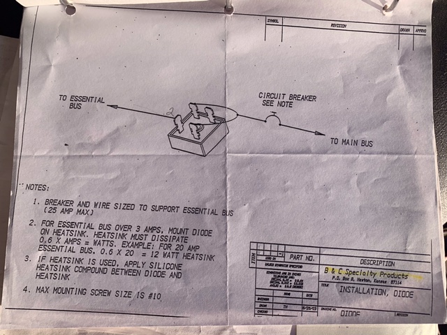
The builder is getting up there in age and it was built 12 years ago but he told me he chose this design so if there was an alternator failure it would transfer automatically. He added that he always thought he should remove the one way diode. The diode diagram is attached. I did remove the diode by disconnecting it but the Stby Alternator regulator and fuse blew.
I can add after 6 months of frustration I have learned a lot about my electrical system. The shunt off of the alternators is incorrect and will be replaced this week. The battery shunt appears to be off by a factor of 2.5. The Garmin draw with only the battery on and both PFDâs tested at 7amps draw while the Garmin displayed 17 amps draw. This implies to me that it needs a 250a and 50mV shunt. I plan on contacting Garmin this week to determine their requirements.
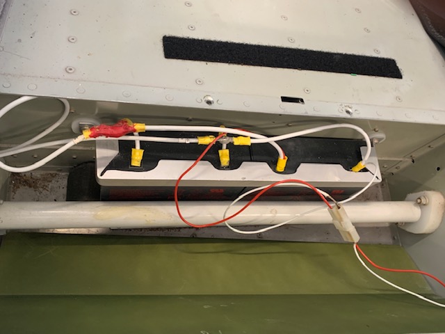
Regarding the two batteries; number 1 is an Odyssey 925 and number two are the wheel chair batteries wired maybe in parallel; picture included. I am not sure these qualify for an alternator all their own? Iâm not sure which way to turn.
With regards to the Z101 option or the Z14 for that matter I am for what ever works best for my current situation. I need to be able to communicate it to my A and P.
William Booth[img]cid:13FCC867-F4FA-4716-B7FB-929F5B9D42DF-L0-001[/img]
| Quote: | On Jan 10, 2021, at 4:26 PM, Robert L. Nuckolls, III <nuckolls.bob(at)aeroelectric.com> wrote:
 Had a little more time to review your drawing.
| Quote: | | My issue is it safe and operationally sound. It is an X design, if that is familiar. |
Not familiar with that designatoin.
| Quote: | Apparently the builder added a bus tie in order to bypass a diode bridge
rectifier type because the draw to recharge the Aux Battery, 2 wheel chair
batteries 7Ah 12v wired in series . . . . |
In series? Parallel maybe?
| Quote: | reduced the essential bus voltage to 12.6v. This bus tie when on,boosts
both busses back to 13.6v. Is this how it was meant to be run? |
The diode WILL drop the voltage by about 0.7 volts
which is insignificant when only e-bus accessories
are being powered. You don't want to charge a battery
through this pathway.
| Quote: | Additionally with both alternators on, the displayed alternator
amperage seems to be all over the scale; sometimes 45-50 amps when
the airplane has most accessories off. Feeding both alternators
into a single âbus barâ seems to cause issues and is that safe? |
TWO alternators don't play well running
in tandem unless their regulators are
specifically chosen for parallel operation.
If you want to run two batteries, then consider
rerouting some wiring to achieve Z14 configuration.
Replace the diode bridge (which is not wired
correctly in the drawing) with a cross-feed
contactor.
Normal Z14 ops call for both alternators
to run all the time independently of each
other on separate systems but with an
ability to share energy between systems
should one alternator fail
| Quote: | | Therefore itâs been recommended that I swap out the Stby Alt for a 60A PP alternator and just use it as the primary power source. |
Don't think that's necessary . . .
| Quote: | My preference would be going to a Z plan where each alternator powers its
own bus but Iâve been advised against that. |
Can't imagine why . . . Z14 was published about 20 years
ago an is flying on a lot of OBAM aircraft. If you
want to keep two batteries, Z-14 is the way to go.
Conversely, you could take some weight out of the
airplane by dropping to one battery and picking
the relevant features of Z101 which is the
decades younger, recommended replacement for Z14
Bob . . .
Un impeachable logic: George Carlin asked, "If black boxes
survive crashes, why don't they make the whole airplane
out of that stuff?"
|
| | - The Matronics AeroElectric-List Email Forum - | | | Use the List Feature Navigator to browse the many List utilities available such as the Email Subscriptions page, Archive Search & Download, 7-Day Browse, Chat, FAQ, Photoshare, and much more:
http://www.matronics.com/Navigator?AeroElectric-List |
|
| Description: |
|
| Filesize: |
67.45 KB |
| Viewed: |
1651 Time(s) |
|
| Description: |
|
| Filesize: |
139.69 KB |
| Viewed: |
1651 Time(s) |
|
|
|
| Back to top |
|
|
nuckolls.bob(at)aeroelect
Guest
|
| Posted: Mon Jan 11, 2021 7:29 am Post subject: RV10 Electrical Issue (w/ Format Clean Up) |
|
|
| Quote: | Garmin specs a 100amp 50mV shunt. Certainly if the shunt and efis settings don't match you'll get inaccurate readings. 7 amps sounds about right to me. Also, I saw the previous comment about fuses in the middle of the sense lines. Excess resistance there will also affect the readings. Fuses are a good idea but they should be right at the shunt. I used pico fuses to avoid issues with a fuse holder.
\ |
There is virtually zero current flowing in the sense
leads off a shunt to the display. Fuses and connectors
in these leads do not adversely affect calibration.
Bob . . .
Un impeachable logic: George Carlin asked, "If black boxes
survive crashes, why don't they make the whole airplane
out of that stuff?"
| | - The Matronics AeroElectric-List Email Forum - | | | Use the List Feature Navigator to browse the many List utilities available such as the Email Subscriptions page, Archive Search & Download, 7-Day Browse, Chat, FAQ, Photoshare, and much more:
http://www.matronics.com/Navigator?AeroElectric-List |
|
|
|
| Back to top |
|
|
|
|
You cannot post new topics in this forum
You cannot reply to topics in this forum
You cannot edit your posts in this forum
You cannot delete your posts in this forum
You cannot vote in polls in this forum
You cannot attach files in this forum
You can download files in this forum
|
Powered by phpBB © 2001, 2005 phpBB Group
|

