 |
Matronics Email Lists
Web Forum Interface to the Matronics Email Lists
|
| View previous topic :: View next topic |
| Author |
Message |
MFleming

Joined: 31 Oct 2017
Posts: 17
|
 Posted: Mon Nov 16, 2020 11:42 am Post subject: Soldering Big Connections Posted: Mon Nov 16, 2020 11:42 am Post subject: Soldering Big Connections |
 |
|
After reading Bob's article on soldering big connection I still have some questions.


Is the wicking of solder down the wire causing a rigid wire for the first inch or so preventable?


Besides a pull test, is it possible to visually recognize a poor solder connection?
| | - The Matronics AeroElectric-List Email Forum - | | | Use the List Feature Navigator to browse the many List utilities available such as the Email Subscriptions page, Archive Search & Download, 7-Day Browse, Chat, FAQ, Photoshare, and much more:
http://www.matronics.com/Navigator?AeroElectric-List |
|
_________________
Michael Fleming |
|
| Back to top |
|
 |
art(at)zemon.name
Guest
|
| Posted: Mon Nov 16, 2020 1:28 pm Post subject: Soldering Big Connections |
|
|
Michael,
Bob's instructions are super complete and very detailed because that's what Bob does so well. I followed his instructions and have now attached two whole connectors so I consider myself an expert.  I can tell you that the process was much simpler and less intimidating that it seemed from reading the instructions. I stood my propane torch up on the table. That left me one hand to get the connector only near enough the flame to melt solder and a second hand to wield the solder. I melted a ton of solder into the connection and, when I was done and things had cooled down, it felt mechanically quite secure. I can tell you that the process was much simpler and less intimidating that it seemed from reading the instructions. I stood my propane torch up on the table. That left me one hand to get the connector only near enough the flame to melt solder and a second hand to wield the solder. I melted a ton of solder into the connection and, when I was done and things had cooled down, it felt mechanically quite secure.
This is a very low risk project. If you try it and get poor results, all you have wasted is a bit of wire and a cheap connector or two. If in doubt, use a short scrap of wire and practice a time or two.
-- Art Z.
On Mon, Nov 16, 2020 at 2:09 PM MFleming <sagriver(at)icloud.com (sagriver(at)icloud.com)> wrote:
| Quote: | --> AeroElectric-List message posted by: "MFleming" <sagriver(at)icloud.com (sagriver(at)icloud.com)>
After reading Bob's article on soldering big connection I still have some questions.
Is the wicking of solder down the wire causing a rigid wire for the first inch or so preventable?
Besides a pull test, is it possible to visually recognize a poor solder connection?
--------
Michael Fleming
|
--
https://CheerfulCurmudgeon.com/Each of us is worth only what we are willing to give away to others. -- Lynn Schusterman
| | - The Matronics AeroElectric-List Email Forum - | | | Use the List Feature Navigator to browse the many List utilities available such as the Email Subscriptions page, Archive Search & Download, 7-Day Browse, Chat, FAQ, Photoshare, and much more:
http://www.matronics.com/Navigator?AeroElectric-List |
|
|
|
| Back to top |
|
|
mikepienaar09(at)gmail.co
Guest
|
| Posted: Mon Nov 16, 2020 1:58 pm Post subject: Soldering Big Connections |
|
|
I wrapped a small piece of fiberfrax around the insulin on the wire and secured it with a small hose clampThis protected the wire insulation from the propane flame completely and made for a very neat installation
Sent from my iPhone
| Quote: | On Nov 16, 2020, at 1:41 PM, Art Zemon <art(at)zemon.name> wrote:
Michael,
Bob's instructions are super complete and very detailed because that's what Bob does so well. I followed his instructions and have now attached two whole connectors so I consider myself an expert. I can tell you that the process was much simpler and less intimidating that it seemed from reading the instructions. I stood my propane torch up on the table. That left me one hand to get the connector only near enough the flame to melt solder and a second hand to wield the solder. I melted a ton of solder into the connection and, when I was done and things had cooled down, it felt mechanically quite secure.
This is a very low risk project. If you try it and get poor results, all you have wasted is a bit of wire and a cheap connector or two. If in doubt, use a short scrap of wire and practice a time or two.
-- Art Z.
On Mon, Nov 16, 2020 at 2:09 PM MFleming <sagriver(at)icloud.com (sagriver(at)icloud.com)> wrote:
| Quote: | --> AeroElectric-List message posted by: "MFleming" <sagriver(at)icloud.com (sagriver(at)icloud.com)>
After reading Bob's article on soldering big connection I still have some questions.
Is the wicking of solder down the wire causing a rigid wire for the first inch or so preventable?
Besides a pull test, is it possible to visually recognize a poor solder connection?
--------
Michael Fleming
|
--
https://CheerfulCurmudgeon.com/Each of us is worth only what we are willing to give away to others. -- Lynn Schusterman
|
| | - The Matronics AeroElectric-List Email Forum - | | | Use the List Feature Navigator to browse the many List utilities available such as the Email Subscriptions page, Archive Search & Download, 7-Day Browse, Chat, FAQ, Photoshare, and much more:
http://www.matronics.com/Navigator?AeroElectric-List |
|
|
|
| Back to top |
|
|
Ceengland
Joined: 11 Oct 2020
Posts: 379
Location: MS
|
| Posted: Mon Nov 16, 2020 2:30 pm Post subject: Soldering Big Connections |
|
|
Addressing the wicking issue: Any wire should be supported a short distance from the termination, so even if the solder wicks up the wire a short distance, the external support will prevent flexing at the end of the "wick'd" area. Remember, *all* joints have stress risers; even crimped joints using PIDG terminals. The metallic insulation grip and the extended nylon terminal insulator assist with moving the bend (stress) point away from the crimp point, but the wire still needs external support.
With a little practice/experience, you can ID an obviously bad solder joint, but if you start with clean conductors and terminals use a bit of electronics-type flux, and keep the wire/terminal stationary while it cools, you'll likely be fine without the ID experience.
An obvious bad joint will often have a rough, dull gray, almost porous appearance on the exposed solder, and will sometimes have a convex appearance rather than concave at the point where the solder meets the copper, where the exposed solder looks analogous to a ball of mercury sitting on a surface instead of flowing out smoothly to meet the surface of the copper.
Charlie
On 11/16/2020 3:25 PM, Art Zemon wrote:
| Quote: | Michael,
Bob's instructions are super complete and very detailed because that's what Bob does so well. I followed his instructions and have now attached two whole connectors so I consider myself an expert. I can tell you that the process was much simpler and less intimidating that it seemed from reading the instructions. I stood my propane torch up on the table. That left me one hand to get the connector only near enough the flame to melt solder and a second hand to wield the solder. I melted a ton of solder into the connection and, when I was done and things had cooled down, it felt mechanically quite secure.
This is a very low risk project. If you try it and get poor results, all you have wasted is a bit of wire and a cheap connector or two. If in doubt, use a short scrap of wire and practice a time or two.
-- Art Z.
On Mon, Nov 16, 2020 at 2:09 PM MFleming <sagriver(at)icloud.com (sagriver(at)icloud.com)> wrote:
| Quote: | --> AeroElectric-List message posted by: "MFleming" <sagriver(at)icloud.com (sagriver(at)icloud.com)>
After reading Bob's article on soldering big connection I still have some questions.
Is the wicking of solder down the wire causing a rigid wire for the first inch or so preventable?
Besides a pull test, is it possible to visually recognize a poor solder connection?
--------
Michael Fleming
|
--
https://CheerfulCurmudgeon.com/ Each of us is worth only what we are willing to give away to others. -- Lynn Schusterman
|
 Virus-free. www.avast.com [url=#DAB4FAD8-2DD7-40BB-A1B8-4E2AA1F9FDF2] [/url] Virus-free. www.avast.com [url=#DAB4FAD8-2DD7-40BB-A1B8-4E2AA1F9FDF2] [/url]
| | - The Matronics AeroElectric-List Email Forum - | | | Use the List Feature Navigator to browse the many List utilities available such as the Email Subscriptions page, Archive Search & Download, 7-Day Browse, Chat, FAQ, Photoshare, and much more:
http://www.matronics.com/Navigator?AeroElectric-List |
|
_________________
Charlie |
|
| Back to top |
|
|
ashleysc(at)broadstripe.n
Guest
|
| Posted: Mon Nov 16, 2020 5:41 pm Post subject: Soldering Big Connections |
|
|
Suggestions:
1. Wrap a band of conductive metal (aluminum is good) around the insulation up close to the fitting and clamp it in place. This forms a heat sink.
2. Use minimal solder flux only on the portion of the bare wire that will be inside the connector.
3. Crimp the connector to remove air space.
4. Add heat and solder from the far end of the connector (end opposite the insulation) only.
5. When the temperature is right the solder will draw into the connector.
6. Stop adding heat and solder when the solder arrives at the insulation.
7. It's OK to quench in cold water.
Cheers! Stu.
From: "Charlie England" <ceengland7(at)gmail.com>
To: aeroelectric-list(at)matronics.com
Sent: Monday, November 16, 2020 2:29:36 PM
Subject: Re: Soldering Big Connections
Addressing the wicking issue: Any wire should be supported a short distance from the termination, so even if the solder wicks up the wire a short distance, the external support will prevent flexing at the end of the "wick'd" area. Remember, *all* joints have stress risers; even crimped joints using PIDG terminals. The metallic insulation grip and the extended nylon terminal insulator assist with moving the bend (stress) point away from the crimp point, but the wire still needs external support.
With a little practice/experience, you can ID an obviously bad solder joint, but if you start with clean conductors and terminals use a bit of electronics-type flux, and keep the wire/terminal stationary while it cools, you'll likely be fine without the ID experience.
An obvious bad joint will often have a rough, dull gray, almost porous appearance on the exposed solder, and will sometimes have a convex appearance rather than concave at the point where the solder meets the copper, where the exposed solder looks analogous to a ball of mercury sitting on a surface instead of flowing out smoothly to meet the surface of the copper.
Charlie
On 11/16/2020 3:25 PM, Art Zemon wrote:
| Quote: | Michael,
Bob's instructions are super complete and very detailed because that's what Bob does so well. I followed his instructions and have now attached two whole connectors so I consider myself an expert. I can tell you that the process was much simpler and less intimidating that it seemed from reading the instructions. I stood my propane torch up on the table. That left me one hand to get the connector only near enough the flame to melt solder and a second hand to wield the solder. I melted a ton of solder into the connection and, when I was done and things had cooled down, it felt mechanically quite secure.
This is a very low risk project. If you try it and get poor results, all you have wasted is a bit of wire and a cheap connector or two. If in doubt, use a short scrap of wire and practice a time or two.
-- Art Z.
On Mon, Nov 16, 2020 at 2:09 PM MFleming <sagriver(at)icloud.com (sagriver(at)icloud.com)> wrote:
| Quote: | --> AeroElectric-List message posted by: "MFleming" <sagriver(at)icloud.com (sagriver(at)icloud.com)>
After reading Bob's article on soldering big connection I still have some questions.
Is the wicking of solder down the wire causing a rigid wire for the first inch or so preventable?
Besides a pull test, is it possible to visually recognize a poor solder connection?
--------
Michael Fleming
|
--
https://CheerfulCurmudgeon.com/ Each of us is worth only what we are willing to give away to others. -- Lynn Schusterman
|
Virus-free. www.avast.com [url=#DAB4FAD8-2DD7-40BB-A1B8-4E2AA1F9FDF2] [/url]
| | - The Matronics AeroElectric-List Email Forum - | | | Use the List Feature Navigator to browse the many List utilities available such as the Email Subscriptions page, Archive Search & Download, 7-Day Browse, Chat, FAQ, Photoshare, and much more:
http://www.matronics.com/Navigator?AeroElectric-List |
|
|
|
| Back to top |
|
|
nuckolls.bob(at)aeroelect
Guest
|
| Posted: Tue Nov 17, 2020 8:50 am Post subject: Soldering Big Connections |
|
|
| Quote: | | With a little practice/experience, you can ID an obviously bad solder joint, but if you start with clean conductors and terminals use a bit of electronics-type flux, and keep the wire/terminal stationary while it cools, you'll likely be fine without the ID experience. |
Most top of the line electronic solders come with
an electronics-friendly flux built in. I have some
cans of zinc-chloride flux around here somewhere . . .
really handy for righteous joinery on sweated copper
fittings . . . but little else.
If your wires/connectors are old then it may be
useful to add some extra flux . . . like this
stuff:
https://tinyurl.com/y2r4klpl
It's a liquid flux dispensed not unlike paint
pens. You can hold the dispensing tip against
your exposed strands and 'pump' out some electrically
friendly flux that will readily wick into the strands.
| Quote: | | An obvious bad joint will often have a rough, dull gray, almost porous appearance on the exposed solder, and will sometimes have a convex appearance rather than concave at the point where the solder meets the copper, where the exposed solder looks analogous to a ball of mercury sitting on a surface instead of flowing out smoothly to meet the surface of the copper. |
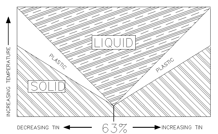
Use only 63/37 (or at worst 60/40) tin-lead solder.
You can't make a 'cold joint' with 63/37 solder
if you tried.
Recall that 63/37 solder's phase diagram has
no 'plastic' range. This means that as the
solder cools, it passes very quickly from
liquid to solid giving you no chance to
scramble the matrix of semi-solid melt
creating a weak and porous mass.
So if you're attempting this fat-wire
termination for the first time, do practice
a bit. Install a couple of terminals on
scrap wire first.
'Wicking' of solder up the running strands
is easy to avoid. Don't get the components to
be joined too hot. Apply heat only to the
terminal concentrating on the end of the
barrel away from the wire. As you feed
what seems like A LOT of solder into the
joint, the FIRST appearance of solder at
the little space between wire insulation
and terminal barrel says STOP. Your done.
Water flows down hill . . . solder flows
from cooler to warmer. Centering your
heat source on the flag-end of the
terminal wire barrel will encourage the
solder flow away only as the materials
to be joined warm up to the solder's
melting point.
Artful crimps depend on a confirmed compatibility
of wire, terminal and crimp tool to achieve
a gas-tight joint. People in the business
for decades can only guarantee THEIR
terminals applied with THEIR tools onto
specified wires. This isn't a brazen
move to capture market share. It's a
warranty of performance backed up by
their laboratory testing.
But consider the solder-filled voids
between terminal barrel, wire strands and
copper wedges called out in the fat-wire
termination article.
I humbly suggest this is the ultimate
example of low-force, gas-tight connection.
Bob . . .
Un impeachable logic: George Carlin asked, "If black boxes
survive crashes, why don't they make the whole airplane
out of that stuff?"
| | - The Matronics AeroElectric-List Email Forum - | | | Use the List Feature Navigator to browse the many List utilities available such as the Email Subscriptions page, Archive Search & Download, 7-Day Browse, Chat, FAQ, Photoshare, and much more:
http://www.matronics.com/Navigator?AeroElectric-List |
|
| Description: |
|
| Filesize: |
218.13 KB |
| Viewed: |
2784 Time(s) |
|
|
|
| Back to top |
|
|
MFleming
Joined: 31 Oct 2017
Posts: 17
|
| Posted: Wed Nov 18, 2020 8:48 pm Post subject: Re: Soldering Big Connections |
|
|
Boy, Bob was right about taking a chunk of wire to the parts store to select the proper size ring connector. The 4 AWG connecters were really sloppy in my 4 AWG welding wire and the 6 AWG connectors were just right.


Well off to the shop I went armed with everyones advice a handful of scrap wire and connectors. I was able to make some very nice connections. The wicking was minimized or non existent. I cut several of them apart, they looked great. I could not separate the sliced in half connector from the wire...it was like it was welded!


Thanks to all


-Michael Fleming
| | - The Matronics AeroElectric-List Email Forum - | | | Use the List Feature Navigator to browse the many List utilities available such as the Email Subscriptions page, Archive Search & Download, 7-Day Browse, Chat, FAQ, Photoshare, and much more:
http://www.matronics.com/Navigator?AeroElectric-List |
|
_________________
Michael Fleming |
|
| Back to top |
|
|
|
|
You cannot post new topics in this forum
You cannot reply to topics in this forum
You cannot edit your posts in this forum
You cannot delete your posts in this forum
You cannot vote in polls in this forum
You cannot attach files in this forum
You can download files in this forum
|
Powered by phpBB © 2001, 2005 phpBB Group
|

