 |
Matronics Email Lists
Web Forum Interface to the Matronics Email Lists
|
| View previous topic :: View next topic |
| Author |
Message |
nuckolls.bob(at)aeroelect
Guest
|
 Posted: Fri Apr 24, 2020 8:59 am Post subject: Alternator field control configurations Posted: Fri Apr 24, 2020 8:59 am Post subject: Alternator field control configurations |
 |
|
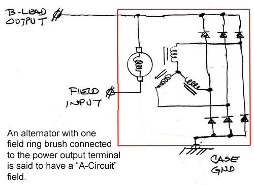
The terms "A-circuit" and "B-circuit" are holdovers from
the days of wound field DC generators. The terms were adopted
to define how voltage applied to the field terminal from
outside affected the output. They've migrated into modern
'alternator speak'.
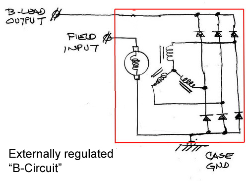
The terms A and B-Circuit are applicable whether the
alternator is internally or externally regulated.
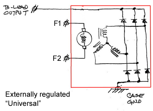
A fifth configuration is always externally regulated
because BOTH field leads are brought out.
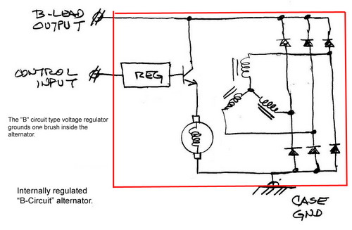
The attached images describe 5 variations of alternator
field wiring:
Bob . . .
| | - The Matronics AeroElectric-List Email Forum - | | | Use the List Feature Navigator to browse the many List utilities available such as the Email Subscriptions page, Archive Search & Download, 7-Day Browse, Chat, FAQ, Photoshare, and much more:
http://www.matronics.com/Navigator?AeroElectric-List |
|
| Description: |
|
| Filesize: |
79.21 KB |
| Viewed: |
3390 Time(s) |
|
| Description: |
|
| Filesize: |
70.16 KB |
| Viewed: |
3390 Time(s) |
|
| Description: |
|
| Filesize: |
68.15 KB |
| Viewed: |
3390 Time(s) |
|
| Description: |
|
| Filesize: |
45.85 KB |
| Viewed: |
3390 Time(s) |
|
| Description: |
|
| Filesize: |
47.67 KB |
| Viewed: |
3390 Time(s) |
|
|
|
| Back to top |
|
 |
ceengland7(at)gmail.com
Guest
|
| Posted: Fri Apr 24, 2020 10:15 am Post subject: Alternator field control configurations |
|
|
On 4/24/2020 11:56 AM, Robert L. Nuckolls, III wrote:
| Quote: | The terms "A-circuit" and "B-circuit" are holdovers from
the days of wound field DC generators. The terms were adopted
to define how voltage applied to the field terminal from
outside affected the output. They've migrated into modern
'alternator speak'.
The terms A and B-Circuit are applicable whether the
alternator is internally or externally regulated.
A fifth configuration is always externally regulated
because BOTH field leads are brought out.
The attached images describe 5 variations of alternator
field wiring:
Bob . . . |
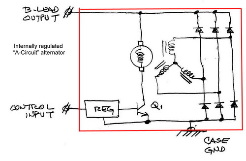
For the new guys, the 'internal regulator A-Circuit' is what you're likely to see in a Nippon Denso (ND) IR alternator.
Q1 in the drawing is, effectively, what keeps us from having positive control via the 'control input'. If Q1 shorts collector to emitter, *or*, if anything inside the regulator block fails and applies full DC voltage to the base of Q1, the alternator 'runs away' in an OV event. I tried repeatedly to explain this to one of the VAF forum members who is quite active in the electronic section of the forum and is supposed to be very knowledgeable, but he adamantly insists that he has full control over his ND alternator via the control terminal. (Even after posting an ND block diagram showing exactly what Bob just showed us.)
I know that at least a few of us monitor both this list and the VAF RV forum. If you're new to electrical/electronic stuff, be very careful about trusting the E/E stuff you read on VAF. Odds of getting correct info over there are closer to a dice roll than a coin flip.
Charlie
 Virus-free. www.avast.com [url=#DAB4FAD8-2DD7-40BB-A1B8-4E2AA1F9FDF2] [/url] Virus-free. www.avast.com [url=#DAB4FAD8-2DD7-40BB-A1B8-4E2AA1F9FDF2] [/url]
| | - The Matronics AeroElectric-List Email Forum - | | | Use the List Feature Navigator to browse the many List utilities available such as the Email Subscriptions page, Archive Search & Download, 7-Day Browse, Chat, FAQ, Photoshare, and much more:
http://www.matronics.com/Navigator?AeroElectric-List |
|
|
|
| Back to top |
|
|
rowlandcarson(at)gmail.co
Guest
|
| Posted: Fri Apr 24, 2020 10:29 am Post subject: Alternator field control configurations |
|
|
On 2020-04-24, at 17:56, Robert L. Nuckolls, III <nuckolls.bob(at)aeroelectric.com> wrote:
| Quote: | The attached images describe 5 variations of alternator
field wiring:
|
Bob - for me just an academic point at present, but which of those corresponds to the Rotax 91X alternator setup, please? It uses an external regulator, the factory-supplied Ducati or the apparently superior Schicke GR6.
in friendship
Rowland
| Rowland Carson ... that's Rowland with a 'w' ...
| <rowlandcarson(at)gmail.com> http://www.rowlandcarson.org.uk
| Skype, Twitter: rowland_carson Facebook: Rowland Carson
| | - The Matronics AeroElectric-List Email Forum - | | | Use the List Feature Navigator to browse the many List utilities available such as the Email Subscriptions page, Archive Search & Download, 7-Day Browse, Chat, FAQ, Photoshare, and much more:
http://www.matronics.com/Navigator?AeroElectric-List |
|
|
|
| Back to top |
|
|
nuckolls.bob(at)aeroelect
Guest
|
| Posted: Fri Apr 24, 2020 10:38 am Post subject: Alternator field control configurations |
|
|
At 01:23 PM 4/24/2020, you wrote:
| Quote: | --> AeroElectric-List message posted by: Rowland Carson <rowlandcarson(at)gmail.com>
On 2020-04-24, at 17:56, Robert L. Nuckolls, III <nuckolls.bob(at)aeroelectric.com> wrote:
> The attached images describe 5 variations of alternator
> field wiring:
Bob - for me just an academic point at present, but which of those corresponds to the Rotax 91X alternator setup, please? It uses an external regulator, the factory-supplied Ducati or the apparently superior Schicke GR6.
in friendship
|
If your talking about an alternator bolted to
the vacuum pump pad, it will no doubt be a
b-circuit, spline drive, pad mounted device.
The alternator INTERNAL to the Rotax is a
permanent magnet, unregulated AC output
alternator that must be paired with a
rectifier/regulator tailored to the task
That's a whole different subject.
Bob . . .
| | - The Matronics AeroElectric-List Email Forum - | | | Use the List Feature Navigator to browse the many List utilities available such as the Email Subscriptions page, Archive Search & Download, 7-Day Browse, Chat, FAQ, Photoshare, and much more:
http://www.matronics.com/Navigator?AeroElectric-List |
|
|
|
| Back to top |
|
|
Dan Fritz
Joined: 02 Apr 2020
Posts: 16
|
| Posted: Fri Apr 24, 2020 10:54 am Post subject: Re: Alternator field control configurations |
|
|
Are the typical ND IR alternators of the Internal Regulator A-Circuit type with the control input simply bonded to the B-lead? If so, then the mod I've performed with the non-conductive screw (in the other thread on Alternator Mods) only gives control in "normal" ops and does not protect from a failed regulator, meaning a b-lead disconnect would still be required. Correct?
| | - The Matronics AeroElectric-List Email Forum - | | | Use the List Feature Navigator to browse the many List utilities available such as the Email Subscriptions page, Archive Search & Download, 7-Day Browse, Chat, FAQ, Photoshare, and much more:
http://www.matronics.com/Navigator?AeroElectric-List |
|
|
|
| Back to top |
|
|
|
|
You cannot post new topics in this forum
You cannot reply to topics in this forum
You cannot edit your posts in this forum
You cannot delete your posts in this forum
You cannot vote in polls in this forum
You cannot attach files in this forum
You can download files in this forum
|
Powered by phpBB © 2001, 2005 phpBB Group
|

