 |
Matronics Email Lists
Web Forum Interface to the Matronics Email Lists
|
| View previous topic :: View next topic |
| Author |
Message |
nuckolls.bob(at)aeroelect
Guest
|
 Posted: Thu Feb 20, 2020 11:18 am Post subject: New role for the E-Bus? Posted: Thu Feb 20, 2020 11:18 am Post subject: New role for the E-Bus? |
 |
|
| Quote: |
Bob, I can count on one hand the number of times I've disagreed with you, but this is wrong and dangerous. I have dual coils on separate switches, so that I can test each one during a run-up. One uses mechanical points, and the other electronic points. They are both on for take-off and landing, but only one for cruise. |
You are quite correct, common sense calls for
independent operability of redundant
SYSTEMS . . . I'm wrestling with a new
computer build. Working to get all my
apps to play nice in Win10.
Sorry 'bout that. Had my head down the wrong
rabbit hole when I penned that. My visual
image during the response was that of
assessing the failure of one coil in
a two coil (waste spark) system. Thanks
for the heads-up!
The usefulness of an endurance bus went
away with Z-12. Went you have two, robust
engine driven power sources the likelihood
of finding it necessary to complete a mission
battery-only becomes one of those 10 to the
minus bazillion risks.
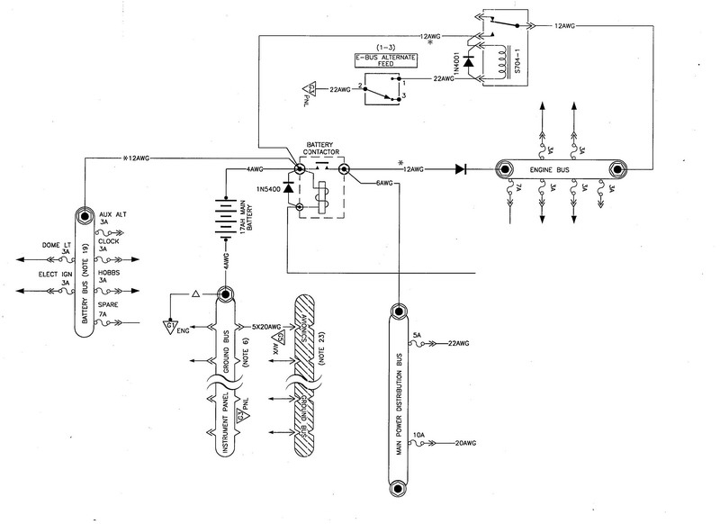
However, if one wishes to honor both (1) legacy
crash safety goal of hitting the dirt with electrics
max cold and (2) independent feeds for the engine,
perhaps the E-Bus finds a new role in Z12 thusly:
[img]cid:.0[/img]
I think this comes close to some alternatives
offered by others in recent days . . .
The reduced reliability of the added relay and wiring
is not a big concern because it's the 'backup'
system. Further, it's easily checked for operability
in pre-flight. Anytime the MAIN bus is up, the ENGINE
bus is up. Finally, the main bus can be taken down
without killing the engine. The normal feed path
to the ENGINE bus has low parts count, no moving
parts and high reliability factor.
Let's thrash this around with a goal of offering
a failure-tolerant energy source to a electrically
dependent engine of any variety.
I noticed that one SDS drawing I've looked at
recently had 5A or smaller fuses for ALL feeders
to their system. Really cool . . .
Bob . . .
| | - The Matronics AeroElectric-List Email Forum - | | | Use the List Feature Navigator to browse the many List utilities available such as the Email Subscriptions page, Archive Search & Download, 7-Day Browse, Chat, FAQ, Photoshare, and much more:
http://www.matronics.com/Navigator?AeroElectric-List |
|
| Description: |
|
| Filesize: |
98.51 KB |
| Viewed: |
12992 Time(s) |
|
|
|
| Back to top |
|
 |
nuckolls.bob(at)aeroelect
Guest
|
| Posted: Thu Feb 20, 2020 11:18 am Post subject: New role for the E-Bus? |
|
|
| Quote: |
Bob, I can count on one hand the number of times I've disagreed with you, but this is wrong and dangerous. I have dual coils on separate switches, so that I can test each one during a run-up. One uses mechanical points, and the other electronic points. They are both on for take-off and landing, but only one for cruise. |
You are quite correct, common sense calls for
independent operability of redundant
SYSTEMS . . . I'm wrestling with a new
computer build. Working to get all my
apps to play nice in Win10.
Sorry 'bout that. Had my head down the wrong
rabbit hole when I penned that. My visual
image during the response was that of
assessing the failure of one coil in
a two coil (waste spark) system. Thanks
for the heads-up!
The usefulness of an endurance bus went
away with Z-12. Went you have two, robust
engine driven power sources the likelihood
of finding it necessary to complete a mission
battery-only becomes one of those 10 to the
minus bazillion risks.
However, if one wishes to honor both (1) legacy
crash safety goal of hitting the dirt with electrics
max cold and (2) independent feeds for the engine,
perhaps the E-Bus finds a new role in Z12 thusly:
[img]cid:.0[/img]
I think this comes close to some alternatives
offered by others in recent days . . .
The reduced reliability of the added relay and wiring
is not a big concern because it's the 'backup'
system. Further, it's easily checked for operability
in pre-flight. Anytime the MAIN bus is up, the ENGINE
bus is up. Finally, the main bus can be taken down
without killing the engine. The normal feed path
to the ENGINE bus has low parts count, no moving
parts and high reliability factor.
Let's thrash this around with a goal of offering
a failure-tolerant energy source to a electrically
dependent engine of any variety.
I noticed that one SDS drawing I've looked at
recently had 5A or smaller fuses for ALL feeders
to their system. Really cool . . .
Bob . . .
| | - The Matronics AeroElectric-List Email Forum - | | | Use the List Feature Navigator to browse the many List utilities available such as the Email Subscriptions page, Archive Search & Download, 7-Day Browse, Chat, FAQ, Photoshare, and much more:
http://www.matronics.com/Navigator?AeroElectric-List |
|
| Description: |
|
| Filesize: |
98.51 KB |
| Viewed: |
12992 Time(s) |

|
|
|
| Back to top |
|
|
nuckolls.bob(at)aeroelect
Guest
|
| Posted: Thu Feb 20, 2020 11:59 am Post subject: New role for the E-Bus? |
|
|
[img]cid:.0[/img]

   P.S.


   Speaking of pre-flight, this arrangement

   would call for going to alternate feed

   and opening the master switch after engine

   start . . . of course this would reboot

   electro-whizzies on the main bus.


   Bob . . .
| | - The Matronics AeroElectric-List Email Forum - | | | Use the List Feature Navigator to browse the many List utilities available such as the Email Subscriptions page, Archive Search & Download, 7-Day Browse, Chat, FAQ, Photoshare, and much more:
http://www.matronics.com/Navigator?AeroElectric-List |
|
| Description: |
|
| Filesize: |
98.64 KB |
| Viewed: |
12992 Time(s) |

|
|
|
| Back to top |
|
|
johnbright
Joined: 14 Dec 2011
Posts: 165
Location: Newport News, VA
|
| Posted: Thu Feb 20, 2020 12:41 pm Post subject: Re: New role for the E-Bus? |
|
|
Proposed SDS EFI+I engine bus preflight:


Close engine bus alternate feed relay from ship's battery.

Energize both fuel pumps.

Read battery voltage on SDS programmer.

Engine bus alternate feed has now been tested at 10 to 11 amps and if main bus did not power on the diode is not shorted.

Close battery contactor.

Open engine bus alternate feed.

If engine bus is still powered, diode is not open.

Close engine bus alternate feed relay.
| | - The Matronics AeroElectric-List Email Forum - | | | Use the List Feature Navigator to browse the many List utilities available such as the Email Subscriptions page, Archive Search & Download, 7-Day Browse, Chat, FAQ, Photoshare, and much more:
http://www.matronics.com/Navigator?AeroElectric-List |
|
_________________
John Bright, RV-6A, at FWF, O-360
Z-101 single batt dual alt SDS EM-5-F.
john_s_bright@yahoo.com, Newport News, Va
N1921R links |
|
| Back to top |
|
|
nuckolls.bob(at)aeroelect
Guest
|
| Posted: Thu Feb 20, 2020 1:17 pm Post subject: New role for the E-Bus? |
|
|
At 02:41 PM 2/20/2020, you wrote:
| Quote: | --> AeroElectric-List message posted by: "johnbright" <john_s_bright(at)yahoo.com>
Proposed SDS EFI+I engine bus preflight:
Close engine bus alternate feed relay from ship's battery.
Energize both fuel pumps.
Read battery voltage on SDS programmer.
Engine bus alternate feed has now been tested at 10 to 11 amps and if main bus did not power on the diode is not shorted.
Close battery contactor.
Open engine bus alternate feed.
If engine bus is still powered, diode is not open.
Close engine bus alternate feed relay. |
Sounds like a plan . . .
Bob . . .
| | - The Matronics AeroElectric-List Email Forum - | | | Use the List Feature Navigator to browse the many List utilities available such as the Email Subscriptions page, Archive Search & Download, 7-Day Browse, Chat, FAQ, Photoshare, and much more:
http://www.matronics.com/Navigator?AeroElectric-List |
|
|
|
| Back to top |
|
|
johnbright
Joined: 14 Dec 2011
Posts: 165
Location: Newport News, VA
|
| Posted: Thu Feb 20, 2020 5:17 pm Post subject: Re: New role for the E-Bus? |
|
|
| nuckolls.bob(at)aeroelect wrote: |
I noticed that one SDS drawing I've looked at
recently had 5A or smaller fuses for ALL feeders
to their system. Really cool . . .
Bob . . . |
Hi Bob,
I would love to see that drawing because SDS recommends 10 A fuses for coilpacks and 15 A fuses for fuel pumps. The Walbro data sheet for the fuel pump shows 5.25 A per pump at 45 psi which is the SDS recommended pressure. SDS says the four cylinder coilpacks draw "just over 1 amp each in cruise at 2,400 rpm".
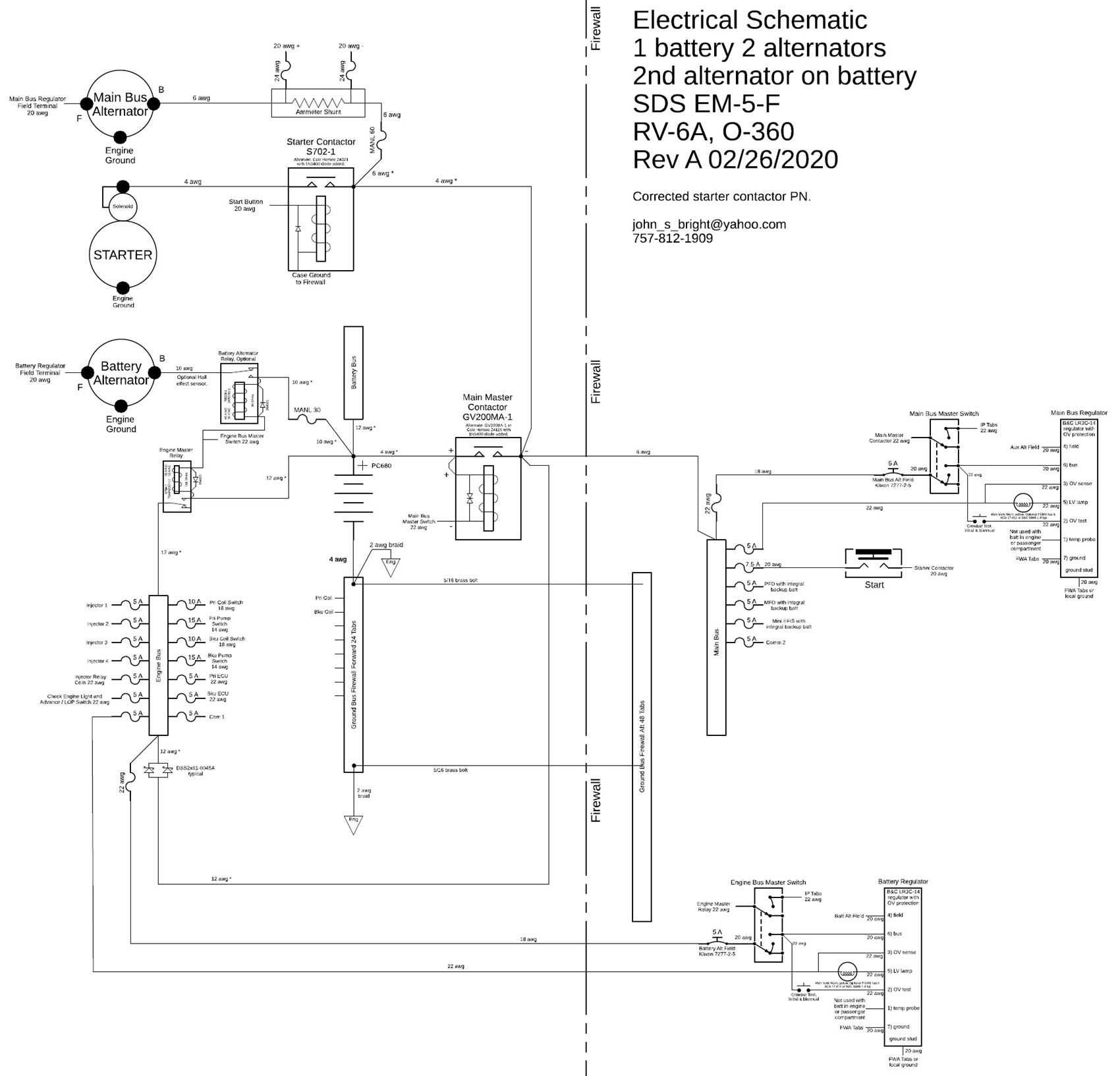
How about connecting the aux alternator to the battery?
| | - The Matronics AeroElectric-List Email Forum - | | | Use the List Feature Navigator to browse the many List utilities available such as the Email Subscriptions page, Archive Search & Download, 7-Day Browse, Chat, FAQ, Photoshare, and much more:
http://www.matronics.com/Navigator?AeroElectric-List |
|
| Description: |
|
| Filesize: |
251.37 KB |
| Viewed: |
12919 Time(s) |
|
_________________
John Bright, RV-6A, at FWF, O-360
Z-101 single batt dual alt SDS EM-5-F.
john_s_bright@yahoo.com, Newport News, Va
N1921R links
Last edited by johnbright on Wed Feb 26, 2020 5:06 am; edited 7 times in total |
|
| Back to top |
|
|
user9253
Joined: 28 Mar 2008
Posts: 1908
Location: Riley TWP Michigan
|
| Posted: Thu Feb 20, 2020 7:00 pm Post subject: Re: New role for the E-Bus? |
|
|
John Bright,

I suggest that the engine bus relay coil be connected to the relay common terminal instead of the relay normally open terminal.

In other words, the relay coil should be powered by the battery, not by the main power bus.
| | - The Matronics AeroElectric-List Email Forum - | | | Use the List Feature Navigator to browse the many List utilities available such as the Email Subscriptions page, Archive Search & Download, 7-Day Browse, Chat, FAQ, Photoshare, and much more:
http://www.matronics.com/Navigator?AeroElectric-List |
|
_________________
Joe Gores |
|
| Back to top |
|
|
johnbright
Joined: 14 Dec 2011
Posts: 165
Location: Newport News, VA
|
| Posted: Thu Feb 20, 2020 7:31 pm Post subject: Re: New role for the E-Bus? |
|
|
| user9253 wrote: | John Bright,
I suggest that the engine bus relay coil be connected to the relay common terminal instead of the relay normally open terminal.
In other words, the relay coil should be powered by the battery, not by the main power bus. |
Thanks Joe!... Silly error on my part. I fixed it.
| | - The Matronics AeroElectric-List Email Forum - | | | Use the List Feature Navigator to browse the many List utilities available such as the Email Subscriptions page, Archive Search & Download, 7-Day Browse, Chat, FAQ, Photoshare, and much more:
http://www.matronics.com/Navigator?AeroElectric-List |
|
_________________
John Bright, RV-6A, at FWF, O-360
Z-101 single batt dual alt SDS EM-5-F.
john_s_bright@yahoo.com, Newport News, Va
N1921R links |
|
| Back to top |
|
|
dfritzj(at)yahoo.com
Guest
|
| Posted: Fri Feb 21, 2020 8:31 am Post subject: New role for the E-Bus? |
|
|
Bob,

Unfortunately, I haven't been able to see the diagram you posted on this (I get the "emacs" on the digest instead of a link).  That said, it sounds like what you're proposing would look an awful lot like the Z13/20 diagram that you toyed with several years back.  Would it provide the architecture we're looking for in this?


Dan


For context:


"....However, if one wishes to honor both (1) legacy

         crash safety goal of hitting the dirt with electrics

         max cold and (2) independent feeds for the engine,

         perhaps the E-Bus finds a new role in Z12 thusly:


      Emacs!


         I think this comes close to some alternatives

         offered by others in recent days . . ."
| | - The Matronics AeroElectric-List Email Forum - | | | Use the List Feature Navigator to browse the many List utilities available such as the Email Subscriptions page, Archive Search & Download, 7-Day Browse, Chat, FAQ, Photoshare, and much more:
http://www.matronics.com/Navigator?AeroElectric-List |
|
|
|
| Back to top |
|
|
user9253
Joined: 28 Mar 2008
Posts: 1908
Location: Riley TWP Michigan
|
|
| Back to top |
|
|
nuckolls.bob(at)aeroelect
Guest
|
| Posted: Fri Feb 21, 2020 10:51 am Post subject: New role for the E-Bus? |
|
|
| Quote: |
Hi Bob,
I would love to see that drawing because SDS recommends 10 A fuses for coilpacks and 15 A fuses for fuel pumps. The Walbro data sheet for the fuel pump shows 5.25 A per pump at 45 psi which is the SDS recommended pressure. SDS says the four cylinder coilpacks draw "just over 1 amp each in cruise at 2,400 rpm".
|
Let me see if I can dig that up again . . . I don't
know if I saved it after discovery a ten or so
days ago when we started this thread.
| Quote: | | In order to meet FAR 23.1361 I add relays for the pumps and coils at the engine bus. |
How about configuring the engine bus as
shown in.
http://www.aeroelectric.com/PPS/Adobe_Architecture_Pdfs/Z01P2-Preliminary.pdf
Now you can run all engine loads through
separate protection and panel mounted switches
while still complying with the max-cold-
during-worst-landings design goal. No
at-the-bus disconnection necessary.
| Quote: | | How about connecting the aux alternator directly to the battery? |
The reason for doing that in Z13/8 was to bypass
the battery contactor thus eliminating that parasitic
load during main-alt-out operations. Given that
we're not offered a much more robust (30A) pad-driven
alternator, such frugality is no longer useful. Hence,
the Z13/8 architecture gives way to Z-12. Simpler
and even holy-watered by the FAA!
I've been gathering some of our thoughts over recent
months into a proposed new Z-figure to replace
Z13 and Z12.
Bob . . .
| | - The Matronics AeroElectric-List Email Forum - | | | Use the List Feature Navigator to browse the many List utilities available such as the Email Subscriptions page, Archive Search & Download, 7-Day Browse, Chat, FAQ, Photoshare, and much more:
http://www.matronics.com/Navigator?AeroElectric-List |
|
|
|
| Back to top |
|
|
ceengland7(at)gmail.com
Guest
|
| Posted: Fri Feb 21, 2020 12:00 pm Post subject: New role for the E-Bus? |
|
|
On Fri, Feb 21, 2020 at 12:57 PM Robert L. Nuckolls, III <nuckolls.bob(at)aeroelectric.com (nuckolls.bob(at)aeroelectric.com)> wrote:
| Quote: | | Quote: |
Hi Bob,
I would love to see that drawing because SDS recommends 10 A fuses for coilpacks and 15 A fuses for fuel pumps. The Walbro data sheet for the fuel pump shows 5.25 A per pump at 45 psi which is the SDS recommended pressure. SDS says the four cylinder coilpacks draw "just over 1 amp each in cruise at 2,400 rpm".
|
 Let me see if I can dig that up again . . . I don't
 know if I saved it after discovery a ten or so
 days ago when we started this thread.
| Quote: | | In order to meet FAR 23.1361 I add relays for the pumps and coils at the engine bus. |
 How about configuring the engine bus as
 shown in.
http://www.aeroelectric.com/PPS/Adobe_Architecture_Pdfs/Z01P2-Preliminary.pdf
 Now you can run all engine loads through
 separate protection and panel mounted switches
 while still complying with the max-cold-
 during-worst-landings design goal. No
 at-the-bus disconnection necessary.
| Quote: | | How about connecting the aux alternator directly to the battery? |
 The reason for doing that in Z13/8 was to bypass
 the battery contactor thus eliminating that parasitic
 load during main-alt-out operations. Given that
 we're not offered a much more robust (30A) pad-driven
 alternator, such frugality is no longer useful. Hence,
 the Z13/8 architecture gives way to Z-12. Simpler
 and even holy-watered by the FAA!
 I've been gathering some of our thoughts over recent
 months into a proposed new Z-figure to replace
 Z13 and Z12.
 Bob . . .
|
I'm on email delivery, and apparently I'm missing a significant % of forum posts.
I'm not following the 'FAR 23' issue with relays at the engine bus for downstream stuff. A fuse at the bus protects everything downstream of the fuse.
When I did failure analysis for my single battery/dual alt, electrically dependent alternative engine, it looked like any conventional arrangement of dual alts with control fed by the main bus and B leads *to* the main bus, would result in the loss of both alts if the master is turned off ('smoke in the cockpit'). I chose to route one alt's B lead directly to the engine bus, making it effectively a dedicated electrical power source for the engine, controlled via the engine bus. Goal was to preserve 'classical' engine independence, and not depend on the limited energy in the battery to complete the flight. There is still a cross-tie switch between engine and main buses, to maintain alt failure redundancy. Is there a problem with this approach?
Charlie
| | - The Matronics AeroElectric-List Email Forum - | | | Use the List Feature Navigator to browse the many List utilities available such as the Email Subscriptions page, Archive Search & Download, 7-Day Browse, Chat, FAQ, Photoshare, and much more:
http://www.matronics.com/Navigator?AeroElectric-List |
|
|
|
| Back to top |
|
|
nuckolls.bob(at)aeroelect
Guest
|
| Posted: Fri Feb 21, 2020 2:14 pm Post subject: New role for the E-Bus? |
|
|
At 10:28 AM 2/21/2020, you wrote:
| Quote: | --> AeroElectric-List message posted by: D Fritz <dfritzj(at)yahoo.com>
Bob,
Unfortunately, I haven't been able to see the diagram you posted on this (I get the "emacs" on the digest instead of a link). That said, it sounds like what you're proposing would look an awful lot like the Z13/20 diagram that you toyed with several years back. Would it provide the architecture we're looking for in this? |
That one is already outdated. Go here
https://tinyurl.com/ukper7j
Bob . . .
| | - The Matronics AeroElectric-List Email Forum - | | | Use the List Feature Navigator to browse the many List utilities available such as the Email Subscriptions page, Archive Search & Download, 7-Day Browse, Chat, FAQ, Photoshare, and much more:
http://www.matronics.com/Navigator?AeroElectric-List |
|
|
|
| Back to top |
|
|
jluckey(at)pacbell.net
Guest
|
| Posted: Fri Feb 21, 2020 4:29 pm Post subject: New role for the E-Bus? |
|
|
Bob,
2 Questions:
1. why is a 30A fuse upstream of a 5A breaker for alternator field?
2. why use a relay for the "clearance delivery" circuit?
-Jeff
On Friday, February 21, 2020, 02:24:56 PM PST, Robert L. Nuckolls, III <nuckolls.bob(at)aeroelectric.com> wrote:
At 10:28 AM 2/21/2020, you wrote:
| Quote: | --> AeroElectric-List message posted by: D Fritz <dfritzj(at)yahoo.com>
Bob,
Unfortunately, I haven't been able to see the diagram you posted on this (I get the "emacs" on the digest instead of a link). That said, it sounds like what you're proposing would look an awful lot like the Z13/20 diagram that you toyed with several years back. Would it provide the architecture we're looking for in this? |
That one is already outdated. Go here
https://tinyurl.com/ukper7j
Bob . . .
| | - The Matronics AeroElectric-List Email Forum - | | | Use the List Feature Navigator to browse the many List utilities available such as the Email Subscriptions page, Archive Search & Download, 7-Day Browse, Chat, FAQ, Photoshare, and much more:
http://www.matronics.com/Navigator?AeroElectric-List |
|
|
|
| Back to top |
|
|
user9253
Joined: 28 Mar 2008
Posts: 1908
Location: Riley TWP Michigan
|
| Posted: Sun Feb 23, 2020 4:07 pm Post subject: Re: New role for the E-Bus? |
|
|
The 30 amp fuse protects the wire running from the bus to the circuit breaker.

It replaces the fuselink in older Z figures.  If the over-volt module shorts out

the circuit, hopefully the 5 amp circuit breaker will trip, but the fuse will not

blow.  A smaller value fuse might blow before the circuit breaker trips.

-

One reason for using a relay is for remote control.  A relay can shut off the

electrical power close to the source instead of running an always hot wire into the cockpit.

Shutting off power at the source might prevent sparks after a forced landing.
| | - The Matronics AeroElectric-List Email Forum - | | | Use the List Feature Navigator to browse the many List utilities available such as the Email Subscriptions page, Archive Search & Download, 7-Day Browse, Chat, FAQ, Photoshare, and much more:
http://www.matronics.com/Navigator?AeroElectric-List |
|
_________________
Joe Gores |
|
| Back to top |
|
|
nuckolls.bob(at)aeroelect
Guest
|
| Posted: Mon Feb 24, 2020 5:05 pm Post subject: New role for the E-Bus? |
|
|
| Quote: |
I'm not following the 'FAR 23' issue with relays at the engine bus for downstream stuff.
A fuse at the bus protects everything downstream of the fuse. |
The 'issue' concerns maximum circuit
protection for always hot feeders. Classically,
the FAA has holy watered 5A as a maximum.
Which doesn't make much sense to me . . .
There's a huge difference in energy released
in a short wire downstream of fuses versus
breakers and 14v vs. 28v.
The legacy backstop was to add disconnect
at the battery . . . relay, contactor etc.
| Quote: | | When I did failure analysis for my single battery/dual alt, electrically dependent alternative engine, it looked like any conventional arrangement of dual alts with control fed by the main bus and B leads *to* the main bus, would result in the loss of both alts if the master is turned off ('smoke in the cockpit'). I chose to route one alt's B lead directly to the engine bus, making it effectively a dedicated electrical power source for the engine, controlled via the engine bus. Goal was to preserve 'classical' engine independence, and not depend on the limited energy in the battery to complete the flight. There is still a cross-tie switch between engine and main buses, to maintain alt failure redundancy. Is there a problem with this approach? |
Don't think so . . . but schematics speak
far more clearly than words. Could you sketch
your architecture and scan or photograph it
for sharing?
Sorry for the delay. Got a 'bug' last Friday
night and I'm just now getting up and around. . .
Bob . . .
| | - The Matronics AeroElectric-List Email Forum - | | | Use the List Feature Navigator to browse the many List utilities available such as the Email Subscriptions page, Archive Search & Download, 7-Day Browse, Chat, FAQ, Photoshare, and much more:
http://www.matronics.com/Navigator?AeroElectric-List |
|
|
|
| Back to top |
|
|
ceengland7(at)gmail.com
Guest
|
| Posted: Mon Feb 24, 2020 6:23 pm Post subject: New role for the E-Bus? |
|
|
On 2/24/2020 7:00 PM, Robert L. Nuckolls, III wrote:
| Quote: | | Quote: |
I'm not following the 'FAR 23' issue with relays at the engine bus for downstream stuff.
A fuse at the bus protects everything downstream of the fuse. |
The 'issue' concerns maximum circuit
protection for always hot feeders. Classically,
the FAA has holy watered 5A as a maximum.
Which doesn't make much sense to me . . .
There's a huge difference in energy released
in a short wire downstream of fuses versus
breakers and 14v vs. 28v.
The legacy backstop was to add disconnect
at the battery . . . relay, contactor etc.
| Quote: | | When I did failure analysis for my single battery/dual alt, electrically dependent alternative engine, it looked like any conventional arrangement of dual alts with control fed by the main bus and B leads *to* the main bus, would result in the loss of both alts if the master is turned off ('smoke in the cockpit'). I chose to route one alt's B lead directly to the engine bus, making it effectively a dedicated electrical power source for the engine, controlled via the engine bus. Goal was to preserve 'classical' engine independence, and not depend on the limited energy in the battery to complete the flight. There is still a cross-tie switch between engine and main buses, to maintain alt failure redundancy. Is there a problem with this approach? |
Don't think so . . . but schematics speak
far more clearly than words. Could you sketch
your architecture and scan or photograph it
for sharing?
Sorry for the delay. Got a 'bug' last Friday
night and I'm just now getting up and around. . .
Bob . . . |
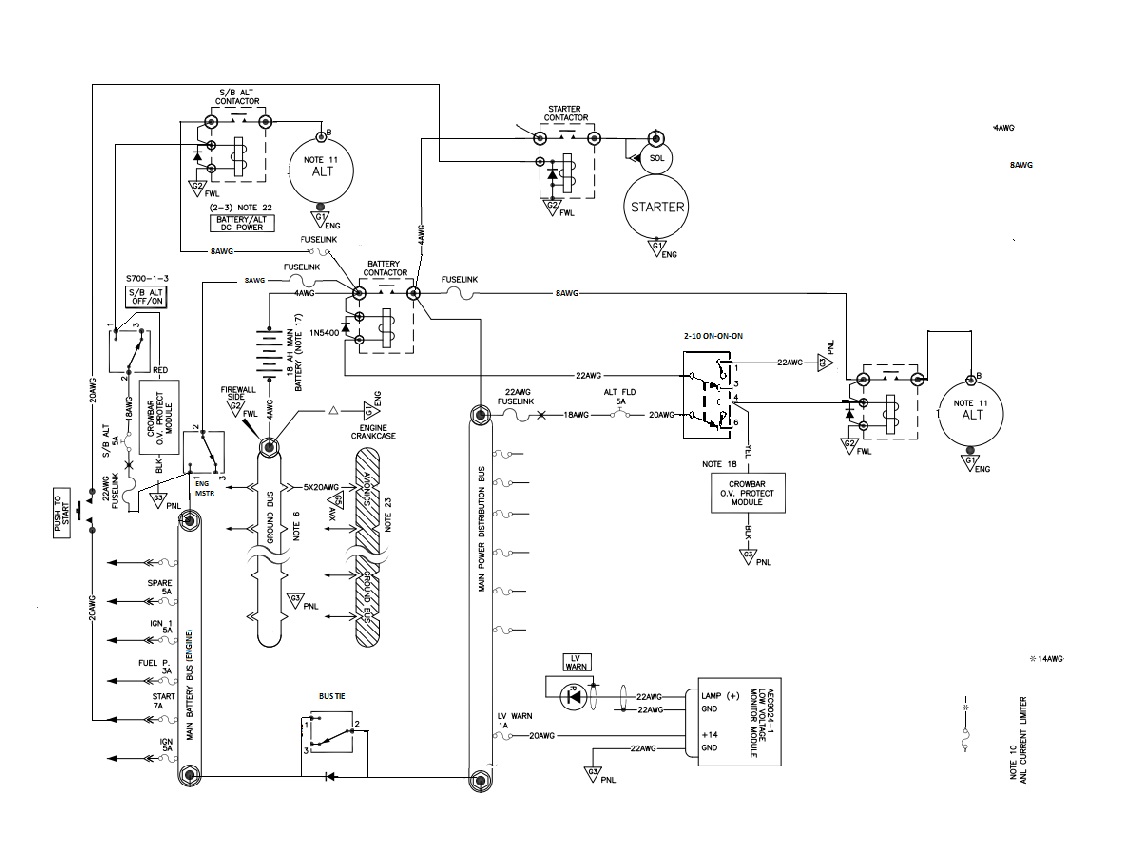
Hi Bob,
RE: the FAR23 issue, I was referring to a drawing posted earlier that had multiple relays fed from a bus which itself was already controlled. Most of the loads could have been handled easily by switches.
To separating the alternator feed-in locations:
Is my thinking incorrect about having both alternators controlled by and fed to the main bus? It seems that shutting off the master would also shut off both alternators. To solve that....
Attached is my MS Paint-abused rough draft, using cut/paste from an Aeroelectric drawing.
Both alts are internally regulated in this drawing (yeah, I know that you're not a fan, but it's ~$150 vs ~$1000, and I won't be randomly flipping alt switches in flight).
All engine related components, and one alternator, are fed from/controlled by the (badly labeled) 'Main Battery Bus (Engine)'. The correct name would be simply 'Engine Bus'.
Everything else, including the other alternator, is fed by the Main bus.
As I said, this is very rough; any labels beyond the basic battery, buses, alternators, and switching are 'artifacts' of the cannibalized original drawing.
Charlie
| | - The Matronics AeroElectric-List Email Forum - | | | Use the List Feature Navigator to browse the many List utilities available such as the Email Subscriptions page, Archive Search & Download, 7-Day Browse, Chat, FAQ, Photoshare, and much more:
http://www.matronics.com/Navigator?AeroElectric-List |
|
| Description: |
|
| Filesize: |
141.24 KB |
| Viewed: |
13005 Time(s) |
|
|
|
| Back to top |
|
|
user9253
Joined: 28 Mar 2008
Posts: 1908
Location: Riley TWP Michigan
|
| Posted: Tue Feb 25, 2020 8:05 am Post subject: Re: New role for the E-Bus? |
|
|
Charlie,

There is no reason to have the start push button connected to the engine bus.

The master contactor must be closed to crank the engine.  So the start button

might as well be connected to the main power bus.

  If the bus tie switch happens to be closed while starting the engine, then

starter current will flow through that switch.  If you must have that switch,

then use a DPDT switch with half of the switch in series with the start push button.

Wire the DPDT switch so that when the bus tie is closed, the starter is disabled.
| | - The Matronics AeroElectric-List Email Forum - | | | Use the List Feature Navigator to browse the many List utilities available such as the Email Subscriptions page, Archive Search & Download, 7-Day Browse, Chat, FAQ, Photoshare, and much more:
http://www.matronics.com/Navigator?AeroElectric-List |
|
_________________
Joe Gores |
|
| Back to top |
|
|
nuckolls.bob(at)aeroelect
Guest
|
| Posted: Tue Feb 25, 2020 8:20 am Post subject: New role for the E-Bus? |
|
|
| Quote: |
I'm not following the 'FAR 23' issue with relays at the engine bus for downstream stuff.
A fuse at the bus protects everything downstream of the fuse. |
The 'issue' concerns maximum circuit
protection for always hot feeders. Classically,
the FAA has holy watered 5A as a maximum.
Which doesn't make much sense to me . . .
There's a huge difference in energy released
in a short wire downstream of fuses versus
breakers and 14v vs. 28v.
The legacy backstop was to add disconnect
at the battery . . . relay, contactor etc.
| Quote: | | When I did failure analysis for my single battery/dual alt, electrically dependent alternative engine, it looked like any conventional arrangement of dual alts with control fed by the main bus and B leads *to* the main bus, would result in the loss of both alts if the master is turned off ('smoke in the cockpit'). I chose to route one alt's B lead directly to the engine bus, making it effectively a dedicated electrical power source for the engine, controlled via the engine bus. Goal was to preserve 'classical' engine independence, and not depend on the limited energy in the battery to complete the flight. There is still a cross-tie switch between engine and main buses, to maintain alt failure redundancy. Is there a problem with this approach? |
Don't think so . . . but schematics speak
far more clearly than words. Could you sketch
your architecture and scan or photograph it
for sharing?
Sorry for the delay. Got a 'bug' last Friday
night and I'm just now getting up and around. . .
Bob . . .
| | - The Matronics AeroElectric-List Email Forum - | | | Use the List Feature Navigator to browse the many List utilities available such as the Email Subscriptions page, Archive Search & Download, 7-Day Browse, Chat, FAQ, Photoshare, and much more:
http://www.matronics.com/Navigator?AeroElectric-List |
|
|
|
| Back to top |
|
|
ceengland7(at)gmail.com
Guest
|
| Posted: Tue Feb 25, 2020 10:57 am Post subject: New role for the E-Bus? |
|
|
On 2/25/2020 10:06 AM, user9253 wrote:
| Quote: |
Charlie,
There is no reason to have the start push button connected to the engine bus.
The master contactor must be closed to crank the engine. So the start button
might as well be connected to the main power bus.
If the bus tie switch happens to be closed while starting the engine, then
starter current will flow through that switch. If you must have that switch,
then use a DPDT switch with half of the switch in series with the start push button.
Wire the DPDT switch so that when the bus tie is closed, the starter is disabled.
--------
Joe Gores
Hi Joe,
|
As I said in the reply to Bob, most of the loads in the drawing are
'artifacts' of copy/paste operations from a basic AEC drawing to my
Paint program. The only items of significance for our discussion at the
moment are the two alternators and the way they connect to the system,
vs connecting both to the main bus as shown in other AEC drawings.
I'll ponder the bus tie issue. The reason it's there is a convenient way
to get alternator/battery to the main bus if there's a failure in the
master control path causing the master contactor to open.
Thanks,
Charlie
| | - The Matronics AeroElectric-List Email Forum - | | | Use the List Feature Navigator to browse the many List utilities available such as the Email Subscriptions page, Archive Search & Download, 7-Day Browse, Chat, FAQ, Photoshare, and much more:
http://www.matronics.com/Navigator?AeroElectric-List |
|
|
|
| Back to top |
|
|
|
|
You cannot post new topics in this forum
You cannot reply to topics in this forum
You cannot edit your posts in this forum
You cannot delete your posts in this forum
You cannot vote in polls in this forum
You cannot attach files in this forum
You can download files in this forum
|
Powered by phpBB © 2001, 2005 phpBB Group
|

