 |
Matronics Email Lists
Web Forum Interface to the Matronics Email Lists
|
| View previous topic :: View next topic |
| Author |
Message |
nuckolls.bob(at)aeroelect
Guest
|
 Posted: Fri Mar 08, 2019 10:02 am Post subject: Landing gear electric actuator circuit Posted: Fri Mar 08, 2019 10:02 am Post subject: Landing gear electric actuator circuit |
 |
|
At 08:50 AM 3/8/2019, you wrote:
| Quote: | --> AeroElectric-List message posted by: "user9253" <fransew(at)gmail.com>
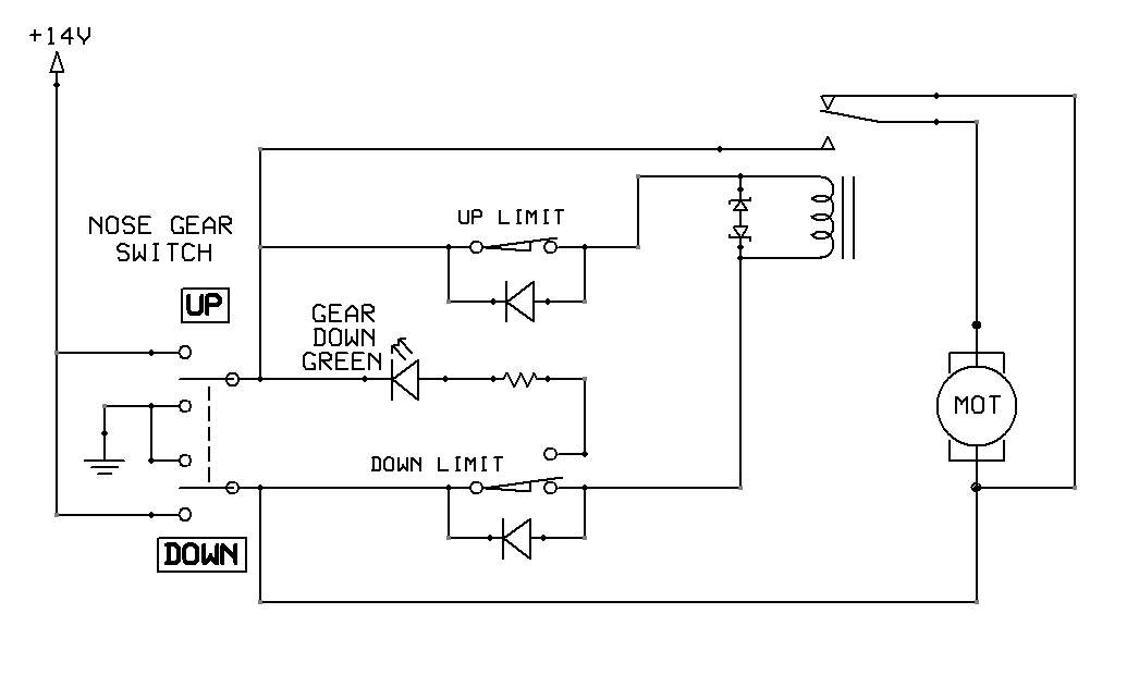
Below is a circuit to lower or raise a landing gear or to control the direction of any small PM DC motor.
The toggle switch controls the motor direction of rotation.
The relay turns the motor on and off.
The limit switches open the relay circuit at end of travel, thus stopping the motor.
Diodes across limit switches allow the current to reverse direction when a limit switch is open.
On the right side, there is an optional emergency switch to lower the gear.
Back to back zener diodes across the relay coil limit inductive voltage spikes.
Disclaimer: The circuit has not yet been proven to work. |
This configuration does not place a hard
short across the motor in the de-energized
condition. This may not be important if
stored kinetic energy on the motor does not
produce an unsatisfactory over-shoot.
Bob . . .
| | - The Matronics AeroElectric-List Email Forum - | | | Use the List Feature Navigator to browse the many List utilities available such as the Email Subscriptions page, Archive Search & Download, 7-Day Browse, Chat, FAQ, Photoshare, and much more:
http://www.matronics.com/Navigator?AeroElectric-List |
|
|
|
| Back to top |
|
 |
user9253
Joined: 28 Mar 2008
Posts: 1908
Location: Riley TWP Michigan
|
| Posted: Fri Mar 08, 2019 11:19 am Post subject: Re: Landing gear electric actuator circuit |
|
|
How about this?

Is the purpose of shorting the motor to bring it to stop it quicker?
| | - The Matronics AeroElectric-List Email Forum - | | | Use the List Feature Navigator to browse the many List utilities available such as the Email Subscriptions page, Archive Search & Download, 7-Day Browse, Chat, FAQ, Photoshare, and much more:
http://www.matronics.com/Navigator?AeroElectric-List |
|
| Description: |
|
| Filesize: |
18.85 KB |
| Viewed: |
4719 Time(s) |
|
_________________
Joe Gores |
|
| Back to top |
|
|
nuckolls.bob(at)aeroelect
Guest
|
| Posted: Fri Mar 08, 2019 4:54 pm Post subject: Landing gear electric actuator circuit |
|
|
| Quote: |
Disclaimer: The circuit has not yet been proven to work. |
This configuration does not place a hard
short across the motor in the de-energized
condition. This may not be important if
stored kinetic energy on the motor does not
produce an unsatisfactory over-shoot.
This is the advantage of using the spdt
relays to control motor power and
controlling relays through the panel
and limit switches.
http://www.aeroelectric.com/PPS/Flight/Flaps/Flaps_4.pdf
[img]cid:.0[/img]
When the energized power relay relaxes,
it throws a dead short on the PM motor.
Back EMF generated in the motor produces
a significant retarding force to the
motor armature.
The nice thing about this configuration
is that dynamic braking occurs whether
motion command is removed by the panel
control switch -OR- a limit switch.
I've been pondering the notion of adding
a 'back up' circuit to supply down-stroke
power to the motor.
Every gear extension system I've encountered
on TC aircraft had a back-up . . . but in
EVERY case, the back-up mechanism was
NON-electric. Some were quite simple and
convenient (Beech Sierra - open valve
in front of pilot's seat. Gear falls and
locks). Some were not so convenient (Beech
Bonanza - Slide pilot's seat all the way
back, passenger seat all the way forward.
Fly left handed while opening door under
passenger seat. Extend handle and put
some rotations on the crank until 'three
greens' are showing. I think it took over
100 revolutions).
The important feature is that normal and
emergency extension systems do not share
any required commodity . . . like electricity.
The gear was MOST likely to fail do to
loss of motor . . . except in the Bonanza
which had a dynamic braking control contactor
with a rather Rube-Goldbergish design.
Bob . . .
| | - The Matronics AeroElectric-List Email Forum - | | | Use the List Feature Navigator to browse the many List utilities available such as the Email Subscriptions page, Archive Search & Download, 7-Day Browse, Chat, FAQ, Photoshare, and much more:
http://www.matronics.com/Navigator?AeroElectric-List |
|
| Description: |
|
| Filesize: |
35.85 KB |
| Viewed: |
4710 Time(s) |
|
|
|
| Back to top |
|
|
nuckolls.bob(at)aeroelect
Guest
|
| Posted: Fri Mar 08, 2019 4:56 pm Post subject: Landing gear electric actuator circuit |
|
|
At 01:19 PM 3/8/2019, you wrote:
Not bad! The only downside I see here
is that the crew control switch carries
motor current . . . which is not a
horrible thing to contemplate.
Bob . . .
| | - The Matronics AeroElectric-List Email Forum - | | | Use the List Feature Navigator to browse the many List utilities available such as the Email Subscriptions page, Archive Search & Download, 7-Day Browse, Chat, FAQ, Photoshare, and much more:
http://www.matronics.com/Navigator?AeroElectric-List |
|
|
|
| Back to top |
|
|
jdubner
Joined: 17 Jul 2012
Posts: 35
Location: Independence, OR
|
| Posted: Sun Mar 10, 2019 5:51 pm Post subject: Re: Landing gear electric actuator circuit |
|
|
| Quote: | This configuration does not place a hard
short across the motor in the de-energized
condition. This may not be important if
stored kinetic energy on the motor does not
produce an unsatisfactory over-shoot. |
I am the OP but have lost track of where we are with all the thread drift. However, for me it is important NOT have a short across the motor when de-energized.
There are two reasons why: with a short there is some back EMF and it contributes to additional force required to mechanically drive the motor by a mechanical means. (There is a 5/16" hex drive that can be turned with a ratchet.) It changes it from just "very difficult" to "impossible", at least in my aircraft.
And with a short across the motor I cannot connect a power source (through a switch) directly to the motor to lower the gear. And that is why I am not happy with the circuit in my original posting.
I've devised an H-bridge circuit with four SPST (or two DPST) relays that does not leave a short across the motor and does not require the switch to handle motor currents (which I've measured at 6 to over 10A (depending on load).
I hope to breadboard the H-bridge version sometime this week using four Omron G8V-1C17T-R-DC12 I have on hand. It's relatively small compared to the Bosch-style relay and has a resistor built in across the coil for arc-suppression.
| | - The Matronics AeroElectric-List Email Forum - | | | Use the List Feature Navigator to browse the many List utilities available such as the Email Subscriptions page, Archive Search & Download, 7-Day Browse, Chat, FAQ, Photoshare, and much more:
http://www.matronics.com/Navigator?AeroElectric-List |
|
_________________
Independence, OR |
|
| Back to top |
|
|
nuckolls.bob(at)aeroelect
Guest
|
| Posted: Mon Mar 11, 2019 4:28 am Post subject: Landing gear electric actuator circuit |
|
|
At 08:51 PM 3/10/2019, you wrote:
| Quote: | --> AeroElectric-List message posted by: "jdubner" <jdubner(at)yahoo.com>I am the OP but have lost track of where we are with all the thread
drift. However, for me it is important NOT have a short across
the motor when de-energized. |
Not sure there was 'drift' so much as
a cooperative sifting of options. I'm
assuming that operating this particular
system without dynamic braking has a
demonstrated track record of satisfactory
operation and service life? I.e. dynamic
braking was shown to be of no value in
meeting design goals?
| Quote: |
There are two reasons why: with a short there is some back EMF and it contributes to additional force required to mechanically drive the motor by a mechanical means. (There is a 5/16" hex drive that can be turned with a ratchet.) It changes it from just "very difficult" to "impossible", at least in my aircraft. |
Yup, did an actuator controller a couple
years ago wherein dynamic braking was necessary
but needed to 'go away' for manual actuation
by hand-crank. That's a pretty easy thing to
do which I can illustrate if you're interested.
| Quote: | | And with a short across the motor I cannot connect a power source (through a switch) directly to the motor to lower the gear. And that is why I am not happy with the circuit in my original posting. |
Electrical failures of a robust design in
this situation will be very rare. Your
system operates say 20 seconds per
flight cycle? 100 flights a year is 2000
seconds or just over 1/2 hour.
Actuation systems in aircraft a generally
qualified at full load and environmental
extremes for thousands of cycles. This
system in your aircraft won't even be
broken in by the time the aircraft is
scrapped.
You have a mechanical backup for the electrical
system so going the extra electrical backup
system seems more a lack of confidence
in the primary system configuration than
a real hedge against a gear-up landing.
| Quote: | | I've devised an H-bridge circuit with four SPST (or two DPST) relays that does not leave a short across the motor and does not require the switch to handle motor currents (which I've measured at 6 to over 10A (depending on load). |
The greatest stress on controls in PM motor
systems isn't the maximum operating draw.
It's INRUSH current over the duration of
contact bounce during closure. While the
motor is spinning up, current through the
circuit may be 3-10 times the running
current. If a contact bounces 5-10 times,
then wear-and-tear on contacts is more
a function of inrush characteristics and
switch mechanics than anything to do with
flight cycles and running current.
| Quote: | | I hope to breadboard the H-bridge version sometime this week using four Omron G8V-1C17T-R-DC12 I have on hand. It's relatively small compared to the Bosch-style relay and has a resistor built in across the coil for arc-suppression. |
Will be interested to see your next iteration . . .
in the mean time, I'll see if I can dig up
the notes on the selective dynamic braking
design.
Bob . . .
| | - The Matronics AeroElectric-List Email Forum - | | | Use the List Feature Navigator to browse the many List utilities available such as the Email Subscriptions page, Archive Search & Download, 7-Day Browse, Chat, FAQ, Photoshare, and much more:
http://www.matronics.com/Navigator?AeroElectric-List |
|
|
|
| Back to top |
|
|
jdubner
Joined: 17 Jul 2012
Posts: 35
Location: Independence, OR
|
| Posted: Mon Mar 11, 2019 6:14 pm Post subject: Re: Landing gear electric actuator circuit |
|
|
| nuckolls.bob(at)aeroelect wrote: | At 08:51 PM 3/10/2019, you wrote:
| Quote: | --> AeroElectric-List message posted by: "jdubner" <jdubner>I am the OP but have lost track of where we are with all the thread
drift. However, for me it is important NOT have a short across
the motor when de-energized. |
Not sure there was 'drift' so much as a cooperative sifting of options. |
You're very charitable, Bob -- I'm totally adrift. There are three separate postings with suggestions ranging from quite useful to eliminating the retractable gear so we'll have to agree to disagree on this.
I'll try to streamline this by listing my constraints and criteria.
1. A mechanical backup would be preferable but is not feasible on this particular Long-EZ. This is because the mechanical drive would need to be located on the center of the instrument panel where the EFIS goes and it would be exceedingly difficult to activate.
2. For backup gear lowering only (not raising) I've decided to connect a power source through a backup gear down switch directly to the motor. No relays, no limit switches, different wires and connections. Same motor, same or different power source (T.B.D. but wired to the battery bus). The motor probably won't fail in my lifetime but the relays, microswitches, and wiring are a different situation.
3. I don't need or want back EMF helping to hold the gear up or down. I know this because I can bounce up and down on the landing gear and it won't budge with or without a short across the motor. But I absolutely, positively must have no short across the motor to implement #2 above.
--
Joe
| | - The Matronics AeroElectric-List Email Forum - | | | Use the List Feature Navigator to browse the many List utilities available such as the Email Subscriptions page, Archive Search & Download, 7-Day Browse, Chat, FAQ, Photoshare, and much more:
http://www.matronics.com/Navigator?AeroElectric-List |
|
_________________
Independence, OR |
|
| Back to top |
|
|
|
|
You cannot post new topics in this forum
You cannot reply to topics in this forum
You cannot edit your posts in this forum
You cannot delete your posts in this forum
You cannot vote in polls in this forum
You cannot attach files in this forum
You can download files in this forum
|
Powered by phpBB © 2001, 2005 phpBB Group
|

