 |
Matronics Email Lists
Web Forum Interface to the Matronics Email Lists
|
| View previous topic :: View next topic |
| Author |
Message |
nuckolls.bob(at)aeroelect
Guest
|
 Posted: Mon Oct 08, 2018 5:10 pm Post subject: A brown-out alternative? Posted: Mon Oct 08, 2018 5:10 pm Post subject: A brown-out alternative? |
 |
|
I mentioned a few days ago that I thought I
had yet another solution to the perennial brown-out
gremlin.
This discussion has been going on for quite some time
and many hours have been expended on a search for the
practical if not elegant solution.
Background:
It seems a number of entrepreneurial suppliers to the
OBAM aircraft industry have introduced devices with desirable
features at prices attractive to the community.
With the advent of PM starters (gawd awful inrush currents)
and a quest for smaller and lighter batteries, the initial
current draw during cranking would depress the battery voltage
to some value where these devices would reset. I think Greg's
Blue Mountain EFIS system was one of the first victims of the
dreaded CBOT(cranking brown out transient).
Many of the first victims were candidates for simple
energy storage networks comprised of super-capacitors. Seems
their current draw was so small and the CBOT so short that
the capacitors would fill in the energy gap.
Over the years it seems that the desire for more energy
over longer CBOTs made the capacitor-storage solution
marginal if not impractical.
Then came some battery based products that offered
both heavier current support during CBOT but let you
do some things like run some electro-whizzies for some time
before cranking the engine.
Only down-side being it adds a battery to the airplane.
Batteries are like house plants . . . mis-treat them slightly
and they will probably recover . . . mis-treat them badly
and they're T.U. Some batteries were ensconced within an
electronic protective shell to reduce probability of
mis-treatment. Good. But it adds to cost.
Then there's the issue of service life. ALL batteries of
any type used for any task on the airplane eventually
need replacement. This feature DEMANDS preventative maintenance
attention from the operator for monitoring condition of
the battery(ies) with go/no-go criteria for replacement.
I've done dozens of FMEA and reliability studies where
adding batteries to the system may have offered builders
some warm-n-fuzzy feelings . . . even to the degree that
they quit worrying about the ship's main battery.
Given that a properly maintained battery is the single
most reliable source of energy on the airplane, it did
not make sense to me that adding more battery(ies) was
more desirable than simply taking care of the battery
you already have . . . and doing the energy studies
to see that its capacity was adequate to all anticipated
flight conditions.
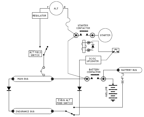
So, with the one-battery per airplane design goal in
mind and CBOTs still lurking in the wings, I would offer
the architecture below for the List's consideration:
[img]cid:.0[/img]
DC to DC up-converters are jelly-bean parts. Dozens
of candidates are available for less than $10 which
will boost 10 or so volts, depressed battery to 14v . . .
well above the roll-over voltage for potential CBOT
victims.
With the architecture shown above, the e-bus boost
feature is available only while the e-bus alternate
feed switch is in the NORMAL position . . . and only
while power is being applied to the starter contactor
via crew controlled push button.
The DC/DC converter can be of any pedigree since
(1) it's never active during normal ops (EMC issues
disappear)
(2) functionality is pre-flight tested every flight
cycle.
(3) It is not a safety of flight issue since it's
only active for tens of milliseconds during
cranking -AND- failure of the converter does
not disable any accessory neeed for comfortable
termination of flight.
(4) Since it is active for perhaps a second each
flight cycle and average utilization of the
light aircraft is less than 100 fligh cycles
per year, the service life of these devices
should exceed lifetime of the airframe.
If there is a 'downside' to this approach, I suppose
that it causes the crew to 'load' the ship's battery
for preflight ops such as ATIS and clearance collection.
But recall that we're assuming that the ship's battery
will be sized and maintained to meet design goals. In
the normal world, cranking the engine takes perhaps 5%
of battery capacity. Preflight ops of electro-whizzies
should require no more than that. That energy will be
replaced in the first few minutes of flight.
I humbly suggest that the technique cited above
will deal with 100% of CBOT issues at zero cost of
ownership beyond initial purchase and installation
of the system and zero impact on system reliability
and performance. It also encourages the owner to
conduct due diligence in the maintenance of the
ship's battery since there are NO standby batteries
tending to lull one into a false sense of system
reliability.
Cogent arguments pro and con are most welcome.
Bob . . .
| | - The Matronics AeroElectric-List Email Forum - | | | Use the List Feature Navigator to browse the many List utilities available such as the Email Subscriptions page, Archive Search & Download, 7-Day Browse, Chat, FAQ, Photoshare, and much more:
http://www.matronics.com/Navigator?AeroElectric-List |
|
| Description: |
|
| Filesize: |
59.17 KB |
| Viewed: |
16269 Time(s) |

|
|
|
| Back to top |
|
 |
art(at)zemon.name
Guest
|
| Posted: Mon Oct 08, 2018 5:48 pm Post subject: A brown-out alternative? |
|
|
Bob,
That looks very clever. I think that it will work.
Is my logic here correct? For my plane, which has two alternators and no endurance bus, I would create an "EFIS" bus, running only the EFIS, and fed via two diodes, one to the main bus and the second to the DC/DC upverter.
For those of us who don't live and breathe this stuff, can you post a few typical part numbers for the upverter and the diodes? Or typical specs?
Thank you for attending to this issue.Â
  -- Art Z.
On Mon, Oct 8, 2018 at 8:28 PM Robert L. Nuckolls, III <nuckolls.bob(at)aeroelectric.com (nuckolls.bob(at)aeroelectric.com)> wrote:
| Quote: | So, with the one-battery per airplane design goal in
mind and CBOTs still lurking in the wings, I would offer
the architecture below for the List's consideration:
[img]cid:.0[/img]
|
--
https://CheerfulCurmudgeon.com/"We do not see the world as it is. We see the world as we are."
| | - The Matronics AeroElectric-List Email Forum - | | | Use the List Feature Navigator to browse the many List utilities available such as the Email Subscriptions page, Archive Search & Download, 7-Day Browse, Chat, FAQ, Photoshare, and much more:
http://www.matronics.com/Navigator?AeroElectric-List |
|
| Description: |
|
| Filesize: |
59.17 KB |
| Viewed: |
16270 Time(s) |

|
| Description: |
|
| Filesize: |
59.17 KB |
| Viewed: |
16270 Time(s) |

|
|
|
| Back to top |
|
|
rnjcurtis(at)charter.net
Guest
|
| Posted: Mon Oct 08, 2018 5:50 pm Post subject: A brown-out alternative? |
|
|
From: Robert L. Nuckolls, III (nuckolls.bob(at)aeroelectric.com)

Sent: Monday, October 8, 2018 9:12 PM

To: aeroelectric-list(at)matronics.com (aeroelectric-list(at)matronics.com)

Subject: A brown-out alternative?


I mentioned a few days ago that I thought I

had yet another solution to the perennial brown-out

gremlin.


This discussion has been going on for quite some time

and many hours have been expended on a search for the

practical if not elegant solution.


Background:


It seems a number of entrepreneurial suppliers to the

OBAM aircraft industry have introduced devices with desirable

features at prices attractive to the community.


With the advent of PM starters (gawd awful inrush currents)

and a quest for smaller and lighter batteries, the initial

current draw during cranking would depress the battery voltage

to some value where these devices would reset. I think Greg's

Blue Mountain EFIS system was one of the first victims of the

dreaded CBOT(cranking brown out transient).


Many of the first victims were candidates for simple

energy storage networks comprised of super-capacitors. Seems

their current draw was so small and the CBOT so short that

the capacitors would fill in the energy gap.


Over the years it seems that the desire for more energy

over longer CBOTs made the capacitor-storage solution

marginal if not impractical.


Then came some battery based products that offered

both heavier current support during CBOT but let you

do some things like run some electro-whizzies for some time

before cranking the engine.


Only down-side being it adds a battery to the airplane.


Batteries are like house plants . . . mis-treat them slightly

and they will probably recover . . . mis-treat them badly

and they're T.U. Some batteries were ensconced within an

electronic protective shell to reduce probability of

mis-treatment. Good. But it adds to cost.


Then there's the issue of service life. ALL batteries of

any type used for any task on the airplane eventually

need replacement. This feature DEMANDS preventative maintenance

attention from the operator for monitoring condition of

the battery(ies) with go/no-go criteria for replacement.


I've done dozens of FMEA and reliability studies where

adding batteries to the system may have offered builders

some warm-n-fuzzy feelings . . . even to the degree that

they quit worrying about the ship's main battery.


Given that a properly maintained battery is the single

most reliable source of energy on the airplane, it did

not make sense to me that adding more battery(ies) was

more desirable than simply taking care of the battery

you already have . . . and doing the energy studies

to see that its capacity was adequate to all anticipated

flight conditions.


So, with the one-battery per airplane design goal in

mind and CBOTs still lurking in the wings, I would offer

the architecture below for the List's consideration:


[img]cid:.0[/img]


DC to DC up-converters are jelly-bean parts. Dozens

of candidates are available for less than $10 which

will boost 10 or so volts, depressed battery to 14v . . .

well above the roll-over voltage for potential CBOT

victims.


With the architecture shown above, the e-bus boost

feature is available only while the e-bus alternate

feed switch is in the NORMAL position . . . and only

while power is being applied to the starter contactor

via crew controlled push button.


The DC/DC converter can be of any pedigree since


(1) it's never active during normal ops (EMC issues

    disappear)


(2) functionality is pre-flight tested every flight

    cycle.


(3) It is not a safety of flight issue since it's

    only active for tens of milliseconds during

    cranking -AND- failure of the converter does

    not disable any accessory neeed for comfortable

    termination of flight.


(4) Since it is active for perhaps a second each

    flight cycle and average utilization of the

    light aircraft is less than 100 fligh cycles

    per year, the service life of these devices

    should exceed lifetime of the airframe.


If there is a 'downside' to this approach, I suppose

that it causes the crew to 'load' the ship's battery

for preflight ops such as ATIS and clearance collection.


But recall that we're assuming that the ship's battery

will be sized and maintained to meet design goals. In

the normal world, cranking the engine takes perhaps 5%

of battery capacity. Preflight ops of electro-whizzies

should require no more than that. That energy will be

replaced in the first few minutes of flight.


I humbly suggest that the technique cited above

will deal with 100% of CBOT issues at zero cost of

ownership beyond initial purchase and installation

of the system and zero impact on system reliability

and performance. It also encourages the owner to

conduct due diligence in the maintenance of the

ship's battery since there are NO standby batteries

tending to lull one into a false sense of system

reliability.


Cogent arguments pro and con are most welcome.


  Bob . . .


Am I correct in assuming that the right hand side of the start push button should be tied through a fuse to the main bus?


Roger
| | - The Matronics AeroElectric-List Email Forum - | | | Use the List Feature Navigator to browse the many List utilities available such as the Email Subscriptions page, Archive Search & Download, 7-Day Browse, Chat, FAQ, Photoshare, and much more:
http://www.matronics.com/Navigator?AeroElectric-List |
|
| Description: |
|
| Filesize: |
59.17 KB |
| Viewed: |
16274 Time(s) |

|
|
|
| Back to top |
|
|
ceengland7(at)gmail.com
Guest
|
| Posted: Mon Oct 08, 2018 6:11 pm Post subject: A brown-out alternative? |
|
|
On 10/8/2018 8:09 PM, Robert L. Nuckolls, III wrote:
| Quote: | I mentioned a few days ago that I thought I
had yet another solution to the perennial brown-out
gremlin.
This discussion has been going on for quite some time
and many hours have been expended on a search for the
practical if not elegant solution.
Background:
It seems a number of entrepreneurial suppliers to the
OBAM aircraft industry have introduced devices with desirable
features at prices attractive to the community.
With the advent of PM starters (gawd awful inrush currents)
and a quest for smaller and lighter batteries, the initial
current draw during cranking would depress the battery voltage
to some value where these devices would reset. I think Greg's
Blue Mountain EFIS system was one of the first victims of the
dreaded CBOT(cranking brown out transient).
Many of the first victims were candidates for simple
energy storage networks comprised of super-capacitors. Seems
their current draw was so small and the CBOT so short that
the capacitors would fill in the energy gap.
Over the years it seems that the desire for more energy
over longer CBOTs made the capacitor-storage solution
marginal if not impractical.
Then came some battery based products that offered
both heavier current support during CBOT but let you
do some things like run some electro-whizzies for some time
before cranking the engine.
Only down-side being it adds a battery to the airplane.
Batteries are like house plants . . . mis-treat them slightly
and they will probably recover . . . mis-treat them badly
and they're T.U. Some batteries were ensconced within an
electronic protective shell to reduce probability of
mis-treatment. Good. But it adds to cost.
Then there's the issue of service life. ALL batteries of
any type used for any task on the airplane eventually
need replacement. This feature DEMANDS preventative maintenance
attention from the operator for monitoring condition of
the battery(ies) with go/no-go criteria for replacement.
I've done dozens of FMEA and reliability studies where
adding batteries to the system may have offered builders
some warm-n-fuzzy feelings . . . even to the degree that
they quit worrying about the ship's main battery.
Given that a properly maintained battery is the single
most reliable source of energy on the airplane, it did
not make sense to me that adding more battery(ies) was
more desirable than simply taking care of the battery
you already have . . . and doing the energy studies
to see that its capacity was adequate to all anticipated
flight conditions.
So, with the one-battery per airplane design goal in
mind and CBOTs still lurking in the wings, I would offer
the architecture below for the List's consideration:
[img]cid:part1.C616506B.5E3BB379(at)gmail.com[/img]
DC to DC up-converters are jelly-bean parts. Dozens
of candidates are available for less than $10 which
will boost 10 or so volts, depressed battery to 14v . . .
well above the roll-over voltage for potential CBOT
victims.
With the architecture shown above, the e-bus boost
feature is available only while the e-bus alternate
feed switch is in the NORMAL position . . . and only
while power is being applied to the starter contactor
via crew controlled push button.
The DC/DC converter can be of any pedigree since
(1) it's never active during normal ops (EMC issues
disappear)
(2) functionality is pre-flight tested every flight
cycle.
(3) It is not a safety of flight issue since it's
only active for tens of milliseconds during
cranking -AND- failure of the converter does
not disable any accessory neeed for comfortable
termination of flight.
(4) Since it is active for perhaps a second each
flight cycle and average utilization of the
light aircraft is less than 100 fligh cycles
per year, the service life of these devices
should exceed lifetime of the airframe.
If there is a 'downside' to this approach, I suppose
that it causes the crew to 'load' the ship's battery
for preflight ops such as ATIS and clearance collection.
But recall that we're assuming that the ship's battery
will be sized and maintained to meet design goals. In
the normal world, cranking the engine takes perhaps 5%
of battery capacity. Preflight ops of electro-whizzies
should require no more than that. That energy will be
replaced in the first few minutes of flight.
I humbly suggest that the technique cited above
will deal with 100% of CBOT issues at zero cost of
ownership beyond initial purchase and installation
of the system and zero impact on system reliability
and performance. It also encourages the owner to
conduct due diligence in the maintenance of the
ship's battery since there are NO standby batteries
tending to lull one into a false sense of system
reliability.
Cogent arguments pro and con are most welcome.
Bob . . . |
I like it; I might try it out on my old RV-4 electrical system. It's a pretty simple, crude system, but the Matronics fuel flow meter reboots on startup. Only potential downside I can see is that some avionics systems may well draw a total of 5 or 6 amps. If battery voltage drops down in the 8-9 volt range, you could see an additional 8 or 10 amps of load on the start PB. There are some planes out there that have the start PB feeding a starter with built-in solenoid/contactor; in those cases, the PB may be pretty heavily loaded.
I toyed with the idea of using one of those 'switchers' to replace the isolation diode if I'd used a dual battery system (instead of the dual alternator system chosen) on my electronic injected engine installation.
Charlie
 Virus-free. www.avast.com [url=#DAB4FAD8-2DD7-40BB-A1B8-4E2AA1F9FDF2] [/url] Virus-free. www.avast.com [url=#DAB4FAD8-2DD7-40BB-A1B8-4E2AA1F9FDF2] [/url]
| | - The Matronics AeroElectric-List Email Forum - | | | Use the List Feature Navigator to browse the many List utilities available such as the Email Subscriptions page, Archive Search & Download, 7-Day Browse, Chat, FAQ, Photoshare, and much more:
http://www.matronics.com/Navigator?AeroElectric-List |
|
| Description: |
|
| Filesize: |
59.17 KB |
| Viewed: |
16274 Time(s) |
|
|
|
| Back to top |
|
|
Eric Page
Joined: 15 Feb 2017
Posts: 243
|
| Posted: Mon Oct 08, 2018 9:55 pm Post subject: Re: A brown-out alternative? |
|
|
| nuckolls.bob(at)aeroelect wrote: | I mentioned a few days ago that I thought I had yet another solution to the perennial brown-out gremlin.
[SNIP]
Cogent arguments pro and con are most welcome. |
Clever idea, Bob -- I like it!
As Charlie mentioned, the current drawn by the DC-DC boost converter could be significant, and would of course increase with decreasing supply voltage. There's also the likelihood of substantial inrush current at start-up. Unless an adequately beefy start switch is specified, its contacts might suffer from making and breaking this load.
This problem might be mitigated by powering the DC-DC boost converter either from the load side of the starter contactor (in parallel with the starter) or via a cube-type automotive relay. This would also simplify adding this design as a retrofit, since the start switch wiring/CB/fuse would not have to be upgraded to carry the boost converter's supply current.
A bit of eBay searching resulted in several potential candidates for the boost converter. These first two are quite small and conveniently packaged; they appear to be the same unit in different enclosures. Power output might be marginal and their 11V max input might be an issue:
https://www.ebay.com/itm/323360110037
https://www.ebay.com/itm/123391340337
These two are significantly more powerful and have a wider input voltage range:
https://www.ebay.com/itm/321795754199
https://www.ebay.com/itm/263796566855
If one didn't want to use an eBay boost converter of unknown quality, Digi-Key offers this unit, which is specified for high vibration and extreme temperatures in railroad use, but doesn't cost a fortune. However, its minimum input is 9V, which might not be low enough in some cases.
https://www.digikey.com/short/jnnh51
Eric
| | - The Matronics AeroElectric-List Email Forum - | | | Use the List Feature Navigator to browse the many List utilities available such as the Email Subscriptions page, Archive Search & Download, 7-Day Browse, Chat, FAQ, Photoshare, and much more:
http://www.matronics.com/Navigator?AeroElectric-List |
|
|
|
| Back to top |
|
|
nuckolls.bob(at)aeroelect
Guest
|
| Posted: Tue Oct 09, 2018 10:12 am Post subject: A brown-out alternative? |
|
|
At 12:55 AM 10/9/2018, you wrote:
| Quote: | --> AeroElectric-List message posted by: "Eric Page" <edpav8r(at)yahoo.com>
nuckolls.bob(at)aeroelect wrote:
> I mentioned a few days ago that I thought I had yet another solution to the perennial brown-out gremlin.
>
> [SNIP]
>
> Cogent arguments pro and con are most welcome.
Clever idea, Bob -- I like it!
As Charlie mentioned, the current drawn by the DC-DC boost converter could be significant, and would of course increase with decreasing supply voltage. There's also the likelihood of substantial inrush current at start-up. Unless an adequately beefy start switch is specified, its contacts might suffer from making and breaking this load.
|
not really a hard-over concern. at 100 flight
cycles per year max, even a marginally 'over taxed'
switch would have a good service life.
Inrush to the dc/dc converter itself wouldn't
be bad either. Remember, the converter is simply
shouldering a load that is already powered up.
| Quote: | | This problem might be mitigated by powering the DC-DC boost converter either from the load side of the starter contactor (in parallel with the starter) or via a cube-type automotive relay. This would also simplify adding this design as a retrofit, since the start switch wiring/CB/fuse would not have to be upgraded to carry the boost converter's supply current. |
I wired it as shown so that in the milliseconds after
start switch closure until the contactor closes, the
converter has time to come up and shoulder the load.
Another feature to be explored is drop out delay in
the starter contactor caused by slow decay of coil
current through the catch diode. When the start
button is release, boost drive goes away.
The start button is held until the engine catches
and starter current drops dramatically. Hopefully
battery voltage will have returned to a value that
supports appliances vulnerable to CBOT.
Somebody mentioned a potential avionics load of 6A?
In the standby (non transmitting mode)? Obviously
a detailed load analysis is indicated.
I am pondering some other power switching protocols with
a goal of seamless integration into the z-figures. But
if puss came to shove, one could simply add an "E-BUS BOOST"
switch that is turned on before engine start and turned
off afterward.
I have one of these for testing https://tinyurl.com/ybqnl8fj
I would set this critter to 15 volts with a 0.7 volt diode
drop to give an e-bus boost of 14.3 volts or thereabouts.
This would be about 2 volts higher than the open circuit
on an SVLA battery.
I'll measure it's ramp up time to make sure it will shoulder
the e-bus in the time it takes for a starter contactor
to close. Don't wait on me for this tho. I'm hip deep in
older commitments. Wanted to give you guys the heads-up
just in case the sum total of our efforts can outpace
what I can offer individually just now.
Bob . . .
| | - The Matronics AeroElectric-List Email Forum - | | | Use the List Feature Navigator to browse the many List utilities available such as the Email Subscriptions page, Archive Search & Download, 7-Day Browse, Chat, FAQ, Photoshare, and much more:
http://www.matronics.com/Navigator?AeroElectric-List |
|
|
|
| Back to top |
|
|
art(at)zemon.name
Guest
|
| Posted: Tue Oct 09, 2018 10:50 am Post subject: A brown-out alternative? |
|
|
On Tue, Oct 9, 2018 at 1:34 PM Robert L. Nuckolls, III <nuckolls.bob(at)aeroelectric.com (nuckolls.bob(at)aeroelectric.com)> wrote:
| Quote: | Somebody mentioned a potential avionics load of 6A?
 In the standby (non transmitting mode)? Obviously
 a detailed load analysis is indicated.
|
Bob,
I did the analysis for am MGL Challenger (10.4 inch display) system with dual screens.
Typical current draw for both screens + iBox + RDAC + AHRS + magnetometer = 2.90 amps
Maximum = 5.64 amps
These numbers are from MGL's documentation; I have not measured them.Â
  -- Art Z.
--
https://CheerfulCurmudgeon.com/"We do not see the world as it is. We see the world as we are."
| | - The Matronics AeroElectric-List Email Forum - | | | Use the List Feature Navigator to browse the many List utilities available such as the Email Subscriptions page, Archive Search & Download, 7-Day Browse, Chat, FAQ, Photoshare, and much more:
http://www.matronics.com/Navigator?AeroElectric-List |
|
|
|
| Back to top |
|
|
nuckolls.bob(at)aeroelect
Guest
|
| Posted: Tue Oct 09, 2018 12:18 pm Post subject: A brown-out alternative? |
|
|
At 01:48 PM 10/9/2018, you wrote:
| Quote: | On Tue, Oct 9, 2018 at 1:34 PM Robert L. Nuckolls, III < nuckolls.bob(at)aeroelectric.com (nuckolls.bob(at)aeroelectric.com)> wrote:
Somebody mentioned a potential avionics load of 6A?
 In the standby (non transmitting mode)? Obviously
 a detailed load analysis is indicated.
Bob,
I did the analysis for am MGL Challenger (10.4 inch display) system with dual screens.
Typical current draw for both screens + iBox + RDAC + AHRS + magnetometer = 2.90 amps
Maximum = 5.64 amps
These numbers are from MGL's documentation; I have not measured them. |
Wow . . . okay. Well, there are BIGGER ones
[img]cid:7.1.0.9.0.20181009151609.05f7fe58(at)aeroelectric.com.0[/img]
Bob . . .
| | - The Matronics AeroElectric-List Email Forum - | | | Use the List Feature Navigator to browse the many List utilities available such as the Email Subscriptions page, Archive Search & Download, 7-Day Browse, Chat, FAQ, Photoshare, and much more:
http://www.matronics.com/Navigator?AeroElectric-List |
|
| Description: |
|
| Filesize: |
196.32 KB |
| Viewed: |
16242 Time(s) |

|
|
|
| Back to top |
|
|
nwparkinson(at)btopenworl
Guest
|
| Posted: Tue Oct 09, 2018 1:22 pm Post subject: A brown-out alternative? |
|
|
Cool !
I have an issue with my P mags during start , Due to my little Li Fe battery during initial cranking the bus voltage drops to 7-8 volts , the engine does not fire until the bus recovers to above 9volts and the ignition comes back on line . ..
If i fitted one of these to my P mag power feed , would that solve it ???
Neil | Quote: | On 9 Oct 2018, at 21:17, Robert L. Nuckolls, III <nuckolls.bob(at)aeroelectric.com (nuckolls.bob(at)aeroelectric.com)> wrote:
At 01:48 PM 10/9/2018, you wrote: | Quote: | | On Tue, Oct 9, 2018 at 1:34 PM Robert L. Nuckolls, III < nuckolls.bob(at)aeroelectric.com (nuckolls.bob(at)aeroelectric.com)> wrote: Somebody mentioned a potential avionics load of 6A? à In the standby (non transmitting mode)? Obviously à a detailed load analysis is indicated. Bob, I did the analysis for am MGL Challenger (10.4 inch display) system with dual screens. Typical current draw for both screens + iBox + RDACà + AHRSà + magnetometerà = 2.90 amps Maximum = 5.64 amps These numbers are from MGL's documentation; I have not measured them. |
Wow . . . okay. Well, there are BIGGER ones <10c8680d.jpg>
Bob . . .
|
| | - The Matronics AeroElectric-List Email Forum - | | | Use the List Feature Navigator to browse the many List utilities available such as the Email Subscriptions page, Archive Search & Download, 7-Day Browse, Chat, FAQ, Photoshare, and much more:
http://www.matronics.com/Navigator?AeroElectric-List |
|
|
|
| Back to top |
|
|
nuckolls.bob(at)aeroelect
Guest
|
| Posted: Tue Oct 09, 2018 2:35 pm Post subject: A brown-out alternative? |
|
|
At 04:20 PM 10/9/2018, you wrote:
| Quote: | Cool !
I have an issue with my P mags during start , Due to my little Li Fe battery during initial cranking the bus voltage drops to 7-8 volts , the engine does not fire until the bus recovers to above 9volts and the ignition comes back on line . ..
If i fitted one of these to my P mag power feed , would that solve it ??? |
Does the bus stay below 9v during cranking?
Normally, the brown-out-transient is a few
tens of milliseconds during starter motor
spin up. If your battery voltage is staying
below 9v after propeller begins to turn,
your battery may be too small or perhaps
worn out.
What kind of battery and starter are you
flying?
But yes, a booster system would take care
of the brown-out condition.
Bob . . .
| | - The Matronics AeroElectric-List Email Forum - | | | Use the List Feature Navigator to browse the many List utilities available such as the Email Subscriptions page, Archive Search & Download, 7-Day Browse, Chat, FAQ, Photoshare, and much more:
http://www.matronics.com/Navigator?AeroElectric-List |
|
|
|
| Back to top |
|
|
nwparkinson(at)btopenworl
Guest
|
| Posted: Tue Oct 09, 2018 2:53 pm Post subject: A brown-out alternative? |
|
|
Iâm have a Skytech starter and a Aerovoltz 12 cell li fe better.
The bus stays below 9 volts for about the first 4 or 5 blades then as the voltage recovers it starts.
Thanks for your help.
On 9 Oct 2018, at 23:33, Robert L. Nuckolls, III <nuckolls.bob(at)aeroelectric.com (nuckolls.bob(at)aeroelectric.com)> wrote:
| Quote: | At 04:20 PM 10/9/2018, you wrote:
| Quote: | Cool !
I have an issue with my P mags during start , Due to my little Li Fe battery during initial cranking the bus voltage drops to 7-8 volts , the engine does not fire until the bus recovers to above 9volts and the ignition comes back on line . ..
If i fitted one of these to my P mag power feed , would that solve it ??? |
Does the bus stay below 9v during cranking?
Normally, the brown-out-transient is a few
tens of milliseconds during starter motor
spin up. If your battery voltage is staying
below 9v after propeller begins to turn,
your battery may be too small or perhaps
worn out.
What kind of battery and starter are you
flying?
But yes, a booster system would take care
of the brown-out condition.
Bob . . . =================================== st">http://www.matronics.com/Navigator?AeroElectric-List =================================== cs.com =================================== om =================================== matronics.com/contribution ===================================
|
| | - The Matronics AeroElectric-List Email Forum - | | | Use the List Feature Navigator to browse the many List utilities available such as the Email Subscriptions page, Archive Search & Download, 7-Day Browse, Chat, FAQ, Photoshare, and much more:
http://www.matronics.com/Navigator?AeroElectric-List |
|
|
|
| Back to top |
|
|
user9253
Joined: 28 Mar 2008
Posts: 1908
Location: Riley TWP Michigan
|
| Posted: Tue Oct 09, 2018 3:27 pm Post subject: Re: A brown-out alternative? |
|
|
Keep in mind that the capabilities of some of the DC-DC converters from China are exaggerated. Compensate for that by purchasing one with a higher rating.
| | - The Matronics AeroElectric-List Email Forum - | | | Use the List Feature Navigator to browse the many List utilities available such as the Email Subscriptions page, Archive Search & Download, 7-Day Browse, Chat, FAQ, Photoshare, and much more:
http://www.matronics.com/Navigator?AeroElectric-List |
|
_________________
Joe Gores |
|
| Back to top |
|
|
Eric Page
Joined: 15 Feb 2017
Posts: 243
|
| Posted: Thu Oct 11, 2018 9:40 pm Post subject: Re: A brown-out alternative? |
|
|
| Bob Nuckolls wrote: | | I wired it as shown so that in the milliseconds after start switch closure until the contactor closes, the converter has time to come up and shoulder the load. |
That makes perfect sense. My suggestion would have caused the DC/DC converter to start up as the bus voltage was sagging, losing the time advantage inherent in your schematic.
| Bob Nuckolls wrote: | I have one of these for testing https://tinyurl.com/ybqnl8fj
I would set this critter to 15 volts with a 0.7 volt diode drop to give an e-bus boost of 14.3 volts or thereabouts. This would be about 2 volts higher than the open circuit on an SVLA battery. |
I saw those too... The 10V minimum input seemed possibly marginal, though you might find that they're happy to work below that level. The converter at this link claims to operate down to 5V and to output 6A.
That said, Joe's comment about exaggerated Chinese specs is right on. Amperes in China seem to contain about half as many electrons as amperes in the rest of the world!
| Bob Nuckolls wrote: | Another feature to be explored is drop out delay in the starter contactor caused by slow decay of coil current through the catch diode. When the start button is released, boost drive goes away.
The start button is held until the engine catches and starter current drops dramatically. Hopefully battery voltage will have returned to a value that supports appliances vulnerable to CBOT. |
If this proved to be a problem, we could craft a system that sequences start events. The attached schematic is my first pass at it. I used a TLC3704 quad comparator (for its push-pull outputs), two relays and a handful of jelly-bean parts. It's a bit of a dog's breakfast, but it should work.
When the start switch is pressed, Q1 turns on, completing a ground path for K1 to energize. The output of comparator U1.1 immediately goes high, which in turn (through the diode-OR network of D2 and D3) causes the output of comparator U1.4 to go low, energizing K2 through Q3, which powers the DC/DC boost converter to support essential avionics. C2 charges through R4, taking about 100mS to reach 7.6V, whereupon the output of comparator U1.2 goes low, energizing K1 through Q2, which in turn energizes the engine starter contactor. C3 charges through blocking diode D1, causing the output of comparator U1.3 to go high, reinforcing the signal at U1.4 pin 10.
When the start switch is released, R1 immdiately turns off Q1, causing K1 to drop out, cutting off the engine starter contactor. R1 also turns off the output of U1.1, but the high at U1.4 pin 10 is held by the output of U1.3. C2 discharges through R4 and the output of U1.1, causing the output of U1.2 to go high (this has no effect, since Q1 has already turned off K1). C3 discharges through R5; after about 100mS C3 drops below 4.4V and the output of U1.3 goes low, causing the output of U1.4 to go high, turning off Q3, K2 and the DC/DC boost converter.
Critiques welcome!
Eric
| | - The Matronics AeroElectric-List Email Forum - | | | Use the List Feature Navigator to browse the many List utilities available such as the Email Subscriptions page, Archive Search & Download, 7-Day Browse, Chat, FAQ, Photoshare, and much more:
http://www.matronics.com/Navigator?AeroElectric-List |
|
| Description: |
|

Download |
| Filename: |
Engine Start Sequencer (Rev A).pdf |
| Filesize: |
37.36 KB |
| Downloaded: |
491 Time(s) |
|
|
| Back to top |
|
|
user9253
Joined: 28 Mar 2008
Posts: 1908
Location: Riley TWP Michigan
|
| Posted: Fri Oct 12, 2018 12:59 am Post subject: Re: A brown-out alternative? |
|
|
The on-delay from energizing a relay plus energizing the starter contactor might be enough without an electronic circuit. Human reaction time will provide an off-delay.
| | - The Matronics AeroElectric-List Email Forum - | | | Use the List Feature Navigator to browse the many List utilities available such as the Email Subscriptions page, Archive Search & Download, 7-Day Browse, Chat, FAQ, Photoshare, and much more:
http://www.matronics.com/Navigator?AeroElectric-List |
|
_________________
Joe Gores |
|
| Back to top |
|
|
nuckolls.bob(at)aeroelect
Guest
|
| Posted: Fri Oct 12, 2018 9:23 am Post subject: A brown-out alternative? |
|
|
At 12:40 AM 10/12/2018, you wrote:
| Quote: | --> AeroElectric-List message posted by: "Eric Page" <edpav8r(at)yahoo.com>
Bob Nuckolls wrote:
> I wired it as shown so that in the milliseconds after start switch closure until the contactor closes, the converter has time to come up and shoulder the load.
That makes perfect sense. My suggestion would have caused the DC/DC converter to start up as the bus voltage was sagging, losing the time advantage inherent in your schematic. |
Good work. Now my concern is that when the starter button
is released, does the boost disappear too soon? i.e. before
the starter contactor releases and unloads the battery?
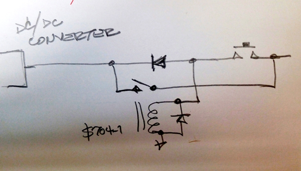
If this is a demonstrated concern, power to the dc/dc
converter might be simply conditioned with a relay thusly:
[img]cid:7.1.0.9.0.20181012121531.05b282e8(at)aeroelectric.com.0[/img]
The S704 relay will have its own drop-out
characteristic which can be crafted to be
LONGER than the starter contactor. If the diode
alone doesn't offer a suitable delay, replace
it with a capacitor . . . no need to 'tailor'
it to any close tolerance . . . 100mS of
dropout delay would not be out of line.
Bob . . .
| | - The Matronics AeroElectric-List Email Forum - | | | Use the List Feature Navigator to browse the many List utilities available such as the Email Subscriptions page, Archive Search & Download, 7-Day Browse, Chat, FAQ, Photoshare, and much more:
http://www.matronics.com/Navigator?AeroElectric-List |
|
| Description: |
|
| Filesize: |
139.05 KB |
| Viewed: |
16147 Time(s) |

|
|
|
| Back to top |
|
|
Eric Page
Joined: 15 Feb 2017
Posts: 243
|
| Posted: Fri Oct 12, 2018 1:59 pm Post subject: Re: A brown-out alternative? |
|
|
| Bob Nuckolls wrote: | | Now my concern is that when the starter button is released, does the boost disappear too soon? i.e. before the starter contactor releases and unloads the battery? |
The circuit does delay shut-off of the boost converter.
Press start button: boost converter powers on immediately, then after ~100mS delay, engine starter spins.
Release start button: engine starter stops immediately, then after ~100mS delay, boost converter shuts off.
The starter-on and booster-off delays are easily customized by adjusting the values of R4 and R5, respectively.
However, your last drawing is certainly a simpler, lower-parts-count solution! Ah well, I still enjoyed thinking it through...
Eric
| | - The Matronics AeroElectric-List Email Forum - | | | Use the List Feature Navigator to browse the many List utilities available such as the Email Subscriptions page, Archive Search & Download, 7-Day Browse, Chat, FAQ, Photoshare, and much more:
http://www.matronics.com/Navigator?AeroElectric-List |
|
|
|
| Back to top |
|
|
nuckolls.bob(at)aeroelect
Guest
|
| Posted: Sat Oct 13, 2018 7:46 am Post subject: A brown-out alternative? |
|
|
| Quote: |
However, your last drawing is certainly a simpler, lower-parts-count solution! Ah well, I still enjoyed thinking it through... |
That's the only way to get 'better' . . . better being
defined as steps toward the elegant solution.
Used to really p-o my techs when I would ask, "okay,
you got it working to spec . . . now . . . how many
parts can you take out and still meet the spec?
Problem was that it was almost never a simple
goal of part reduction, it often called for
an alternate approach.
In this case, I'd like to evolve an approach
that appeals to the largest audience. Especially
those with limited hands-on, DIY skills for
electronic fabrication. Using a relay to achieve
sequencing goals is pretty crude . . . but the
simplicity is appealing.
Bob . . .
| | - The Matronics AeroElectric-List Email Forum - | | | Use the List Feature Navigator to browse the many List utilities available such as the Email Subscriptions page, Archive Search & Download, 7-Day Browse, Chat, FAQ, Photoshare, and much more:
http://www.matronics.com/Navigator?AeroElectric-List |
|
|
|
| Back to top |
|
|
BARRY CHECK 6
Joined: 15 Mar 2011
Posts: 738
|
| Posted: Sat Oct 13, 2018 10:07 am Post subject: A brown-out alternative? |
|
|
WHOOPS LEFT HAND SIDE?
On Sat, Oct 13, 2018 at 2:00 PM FLYaDIVE <flyadive(at)gmail.com (flyadive(at)gmail.com)> wrote:
| Quote: | Bob:
Just a quickie...
Looking at the schematic...
B+ coming in on the Right Hand Side?
If so, wouldn't the relay be energized all the time the B+ is turned on?
And the momentary switch not being required?
Barry
On Fri, Oct 12, 2018 at 1:28 PM Robert L. Nuckolls, III <nuckolls.bob(at)aeroelectric.com (nuckolls.bob(at)aeroelectric.com)> wrote:
| Quote: | At 12:40 AM 10/12/2018, you wrote:
| Quote: | --> AeroElectric-List message posted by: "Eric Page" <edpav8r(at)yahoo.com (edpav8r(at)yahoo.com)>
Bob Nuckolls wrote:
> I wired it as shown so that in the milliseconds after start switch closure until the contactor closes, the converter has time to come up and shoulder the load.
That makes perfect sense. My suggestion would have caused the DC/DC converter to start up as the bus voltage was sagging, losing the time advantage inherent in your schematic. |
 Good work. Now my concern is that when the starter button
 is released, does the boost disappear too soon? i.e. before
 the starter contactor releases and unloads the battery?
Â
 If this is a demonstrated concern, power to the dc/dc
 converter might be simply conditioned with a relay thusly:
[img]cid:7.1.0.9.0.20181012121531.05b282e8(at)aeroelectric.com.0[/img]
 The S704 relay will have its own drop-out
 characteristic which can be crafted to be
 LONGER than the starter contactor. If the diode
 alone doesn't offer a suitable delay, replace
 it with a capacitor . . . no need to 'tailor'
 it to any close tolerance . . . 100mS of
 dropout delay would not be out of line.
 Bob . . .
|
|
| | - The Matronics AeroElectric-List Email Forum - | | | Use the List Feature Navigator to browse the many List utilities available such as the Email Subscriptions page, Archive Search & Download, 7-Day Browse, Chat, FAQ, Photoshare, and much more:
http://www.matronics.com/Navigator?AeroElectric-List |
|
| Description: |
|
| Filesize: |
139.05 KB |
| Viewed: |
16123 Time(s) |

|
| Description: |
|
| Filesize: |
139.05 KB |
| Viewed: |
16123 Time(s) |
|
|
|
| Back to top |
|
|
BARRY CHECK 6
Joined: 15 Mar 2011
Posts: 738
|
| Posted: Sat Oct 13, 2018 10:13 am Post subject: A brown-out alternative? |
|
|
Bob:
Just a quickie...
Looking at the schematic...
B+ coming in on the Right Hand Side?
If so, wouldn't the relay be energized all the time the B+ is turned on?
And the momentary switch not being required?
Barry
On Fri, Oct 12, 2018 at 1:28 PM Robert L. Nuckolls, III <nuckolls.bob(at)aeroelectric.com (nuckolls.bob(at)aeroelectric.com)> wrote:
| Quote: | At 12:40 AM 10/12/2018, you wrote:
| Quote: | --> AeroElectric-List message posted by: "Eric Page" <edpav8r(at)yahoo.com (edpav8r(at)yahoo.com)>
Bob Nuckolls wrote:
> I wired it as shown so that in the milliseconds after start switch closure until the contactor closes, the converter has time to come up and shoulder the load.
That makes perfect sense. My suggestion would have caused the DC/DC converter to start up as the bus voltage was sagging, losing the time advantage inherent in your schematic. |
 Good work. Now my concern is that when the starter button
 is released, does the boost disappear too soon? i.e. before
 the starter contactor releases and unloads the battery?
Â
 If this is a demonstrated concern, power to the dc/dc
 converter might be simply conditioned with a relay thusly:
[img]cid:7.1.0.9.0.20181012121531.05b282e8(at)aeroelectric.com.0[/img]
 The S704 relay will have its own drop-out
 characteristic which can be crafted to be
 LONGER than the starter contactor. If the diode
 alone doesn't offer a suitable delay, replace
 it with a capacitor . . . no need to 'tailor'
 it to any close tolerance . . . 100mS of
 dropout delay would not be out of line.
 Bob . . .
|
| | - The Matronics AeroElectric-List Email Forum - | | | Use the List Feature Navigator to browse the many List utilities available such as the Email Subscriptions page, Archive Search & Download, 7-Day Browse, Chat, FAQ, Photoshare, and much more:
http://www.matronics.com/Navigator?AeroElectric-List |
|
| Description: |
|
| Filesize: |
139.05 KB |
| Viewed: |
16123 Time(s) |

|
| Description: |
|
| Filesize: |
139.05 KB |
| Viewed: |
16123 Time(s) |

|
|
|
| Back to top |
|
|
donvansanten(at)gmail.com
Guest
|
| Posted: Sat Oct 13, 2018 10:27 am Post subject: A brown-out alternative? |
|
|
Barry, B+ is on the right side and I belive the momentary switch is the starter switch.
On Sat, Oct 13, 2018, 11:13 FLYaDIVE <flyadive(at)gmail.com (flyadive(at)gmail.com)> wrote:
| Quote: | WHOOPS LEFT HAND SIDE?
On Sat, Oct 13, 2018 at 2:00 PM FLYaDIVE <flyadive(at)gmail.com (flyadive(at)gmail.com)> wrote:
| Quote: | Bob:
Just a quickie...
Looking at the schematic...
B+ coming in on the Right Hand Side?
If so, wouldn't the relay be energized all the time the B+ is turned on?
And the momentary switch not being required?
Barry
On Fri, Oct 12, 2018 at 1:28 PM Robert L. Nuckolls, III <nuckolls.bob(at)aeroelectric.com (nuckolls.bob(at)aeroelectric.com)> wrote:
| Quote: | At 12:40 AM 10/12/2018, you wrote:
| Quote: | --> AeroElectric-List message posted by: "Eric Page" <edpav8r(at)yahoo.com (edpav8r(at)yahoo.com)>
Bob Nuckolls wrote:
> I wired it as shown so that in the milliseconds after start switch closure until the contactor closes, the converter has time to come up and shoulder the load.
That makes perfect sense. My suggestion would have caused the DC/DC converter to start up as the bus voltage was sagging, losing the time advantage inherent in your schematic. |
 Good work. Now my concern is that when the starter button
 is released, does the boost disappear too soon? i.e. before
 the starter contactor releases and unloads the battery?
Â
 If this is a demonstrated concern, power to the dc/dc
 converter might be simply conditioned with a relay thusly:
 The S704 relay will have its own drop-out
 characteristic which can be crafted to be
 LONGER than the starter contactor. If the diode
 alone doesn't offer a suitable delay, replace
 it with a capacitor . . . no need to 'tailor'
 it to any close tolerance . . . 100mS of
 dropout delay would not be out of line.
 Bob . . .
|
|
|
| | - The Matronics AeroElectric-List Email Forum - | | | Use the List Feature Navigator to browse the many List utilities available such as the Email Subscriptions page, Archive Search & Download, 7-Day Browse, Chat, FAQ, Photoshare, and much more:
http://www.matronics.com/Navigator?AeroElectric-List |
|
|
|
| Back to top |
|
|
|
|
You cannot post new topics in this forum
You cannot reply to topics in this forum
You cannot edit your posts in this forum
You cannot delete your posts in this forum
You cannot vote in polls in this forum
You cannot attach files in this forum
You can download files in this forum
|
Powered by phpBB © 2001, 2005 phpBB Group
|

