 |
Matronics Email Lists
Web Forum Interface to the Matronics Email Lists
|
| View previous topic :: View next topic |
| Author |
Message |
art(at)zemon.name
Guest
|
 Posted: Mon Jun 04, 2018 6:41 pm Post subject: How to Wire My Alternator Posted: Mon Jun 04, 2018 6:41 pm Post subject: How to Wire My Alternator |
 |
|
I need help. I bought a used engine and it came with an alternator that has no labels that I can find. How do I hook it up?
Engine: Lycoming IO-360-A1A
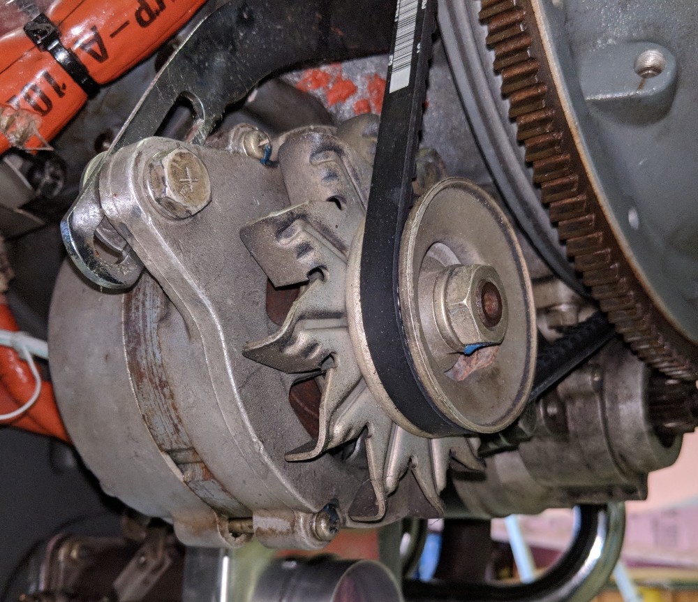
Alternator: looks like this:
[img]cid:ii_ji12srt00_163cdd044737ee71[/img]
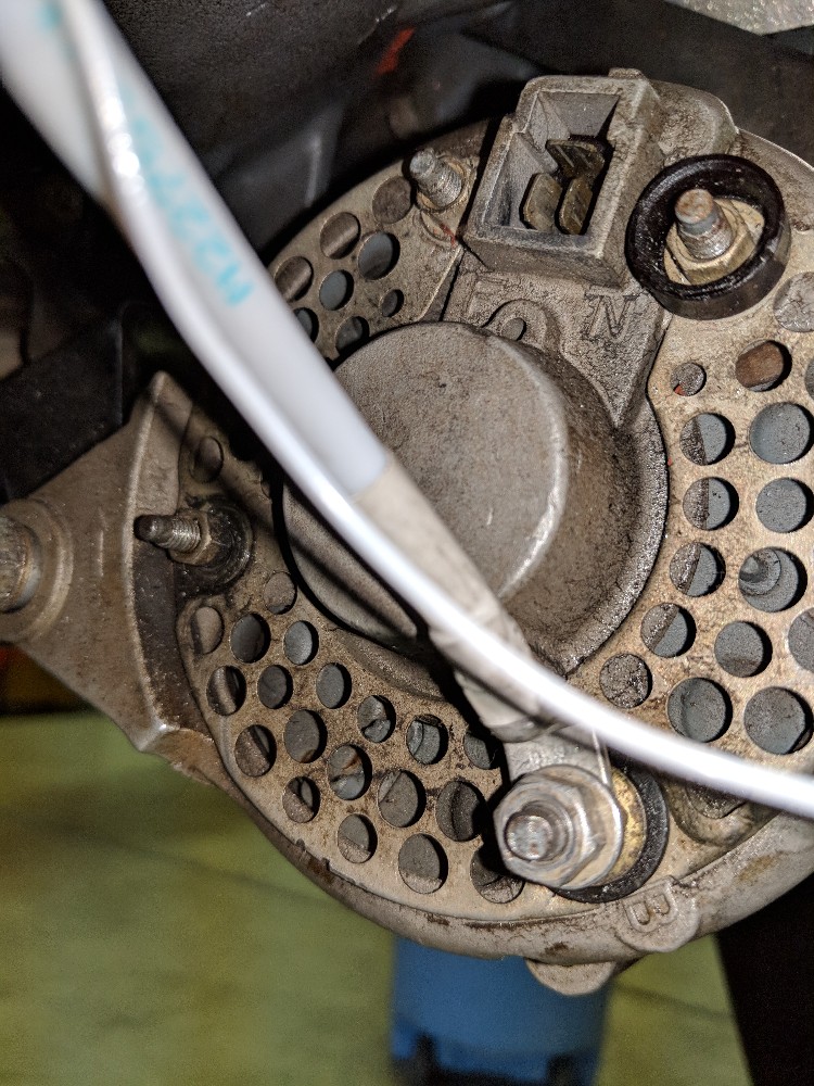
Back of the alternator has three Faston tabs and what looks like a screw terminal next to them:
[img]cid:ii_ji12tk0g2_163cdd0d21dfc1df[/img]
I bought a B&C LR3C-14 voltage regulator and ran the field wire to one of the Faston tabs. I have confirmed that I do have voltage at the alternator end of the wire. However, with the engine off, my EFIS does not show any current draw when I turn on the primary alternator. When I run the engine, the primary alternator does not produce any current.
I also have a B&C standby alternator with its B&C voltage regulator. That one works just fine. With the engine off, I see it's field draw about 0.5 amps. With the engine running, the standby alternator pumps out plenty of amps which the EFIS nicely displays.
How should I connect the primary alternator? And what is it?
Thanks,
-- Art Z.
--
https://CheerfulCurmudgeon.com/"We do not see the world as it is. We see the world as we are."
| | - The Matronics AeroElectric-List Email Forum - | | | Use the List Feature Navigator to browse the many List utilities available such as the Email Subscriptions page, Archive Search & Download, 7-Day Browse, Chat, FAQ, Photoshare, and much more:
http://www.matronics.com/Navigator?AeroElectric-List |
|
| Description: |
|
| Filesize: |
265.29 KB |
| Viewed: |
4041 Time(s) |
|
| Description: |
|
| Filesize: |
255.33 KB |
| Viewed: |
4041 Time(s) |

|
|
|
| Back to top |
|
 |
ceengland7(at)gmail.com
Guest
|
| Posted: Mon Jun 04, 2018 7:27 pm Post subject: How to Wire My Alternator |
|
|
On 6/4/2018 9:40 PM, Art Zemon wrote:
| Quote: | I need help. I bought a used engine and it came with an alternator that has no labels that I can find. How do I hook it up?
Engine: Lycoming IO-360-A1A
Alternator: looks like this:
Back of the alternator has three Faston tabs and what looks like a screw terminal next to them:
I bought a B&C LR3C-14 voltage regulator and ran the field wire to one of the Faston tabs. I have confirmed that I do have voltage at the alternator end of the wire. However, with the engine off, my EFIS does not show any current draw when I turn on the primary alternator. When I run the engine, the primary alternator does not produce any current.
I also have a B&C standby alternator with its B&C voltage regulator. That one works just fine. With the engine off, I see it's field draw about 0.5 amps. With the engine running, the standby alternator pumps out plenty of amps which the EFIS nicely displays.
How should I connect the primary alternator? And what is it?
Thanks,
-- Art Z.
|
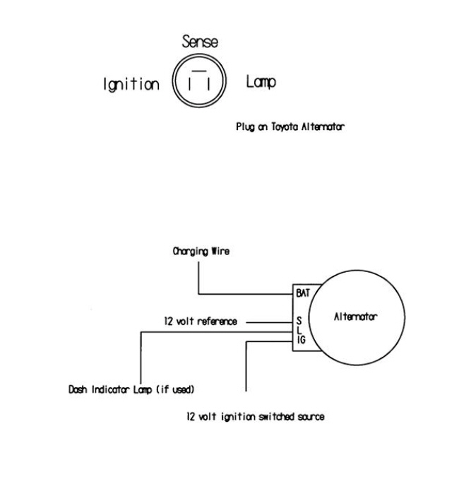
That *looks* like one of the early internally regulated alternators. If I'm right, it needs to see 12V on the 'I' (or 'IG', for Ignition) terminal to 'turn on'. I'm attaching a drawing (let me know if it doesn't come through) of a similar alternator. the 3 pin shell is shaped differently, but I believe that the pinout is the same. On the rather primitive electrical system I had, the IG pin was simply jumped to the B lead terminal. Not advising you to operate it that way, but you can test for operation by doing that. If you jump from B lead to IG, start the engine, and get ~14V out on the B lead, then you have an internally regulated alternator.
Note that I might be wrong; be sure none of your avionics are connected when you do this test....
Charlie
[img]cid:part1.92F0004C.98A4EFBA(at)gmail.com[/img]
 Virus-free. www.avast.com [url=#DAB4FAD8-2DD7-40BB-A1B8-4E2AA1F9FDF2] [/url] Virus-free. www.avast.com [url=#DAB4FAD8-2DD7-40BB-A1B8-4E2AA1F9FDF2] [/url]
| | - The Matronics AeroElectric-List Email Forum - | | | Use the List Feature Navigator to browse the many List utilities available such as the Email Subscriptions page, Archive Search & Download, 7-Day Browse, Chat, FAQ, Photoshare, and much more:
http://www.matronics.com/Navigator?AeroElectric-List |
|
| Description: |
|
| Filesize: |
42.29 KB |
| Viewed: |
4039 Time(s) |
|
|
|
| Back to top |
|
|
yellowduckduo(at)gmail.co
Guest
|
| Posted: Tue Jun 05, 2018 4:12 am Post subject: How to Wire My Alternator |
|
|
It also *looks* like it could even be one of the millions of old
externally regulated ND units so you might be able to confirm the field
coil connections with an ohmeter.
I have one here that brought out both sides of the field to the 3 pin
connector IIRC. Usually there is a data plate with a part number that
can be googled.
Regardless before or after getting it to work, I would consider taking
it apart to confirm good brushes and slip rings, and probably put in new
bearings before I'd fly it.
Ken
On 04/06/2018 11:27 PM, Charlie England wrote:
| Quote: | On 6/4/2018 9:40 PM, Art Zemon wrote:
> I need help. I bought a used engine and it came with an alternator
> that has no labels that I can find. How do I hook it up?
>
> Engine: Lycoming IO-360-A1A
>
> Alternator: looks like this:
> Back of the alternator has three Faston tabs and what looks like a
> screw terminal next to them:
>
>
> I bought a B&C LR3C-14 voltage regulator and ran the field wire to
> one of the Faston tabs. I have confirmed that I do have voltage at
> the alternator end of the wire. However, with the engine off, my EFIS
> does not show any current draw when I turn on the primary alternator.
> When I run the engine, the primary alternator does not produce any
> current.
>
> I also have a B&C standby alternator with its B&C voltage regulator.
> That one works just fine. With the engine off, I see it's field draw
> about 0.5 amps. With the engine running, the standby alternator pumps
> out plenty of amps which the EFIS nicely displays.
>
> How should I connect the primary alternator? And what is it?
>
> Thanks,
> -- Art Z.
>
That *looks* like one of the early internally regulated alternators.
If I'm right, it needs to see 12V on the 'I' (or 'IG', for Ignition)
terminal to 'turn on'. I'm attaching a drawing (let me know if it
doesn't come through) of a similar alternator. the 3 pin shell is
shaped differently, but I believe that the pinout is the same. On the
rather primitive electrical system I had, the IG pin was simply jumped
to the B lead terminal. Not advising you to operate it that way, but
you can test for operation by doing that. If you jump from B lead to
IG, start the engine, and get ~14V out on the B lead, then you have an
internally regulated alternator.
Note that I might be wrong; be sure none of your avionics are
connected when you do this test....
Charlie
<https://www.avast.com/sig-email?utm_medium=email&utm_source=link&utm_campaign=sig-email&utm_content=emailclient&utm_term=icon>
Virus-free. www.avast.com
<https://www.avast.com/sig-email?utm_medium=email&utm_source=link&utm_campaign=sig-email&utm_content=emailclient&utm_term=link>
<#DAB4FAD8-2DD7-40BB-A1B8-4E2AA1F9FDF2>
|
| | - The Matronics AeroElectric-List Email Forum - | | | Use the List Feature Navigator to browse the many List utilities available such as the Email Subscriptions page, Archive Search & Download, 7-Day Browse, Chat, FAQ, Photoshare, and much more:
http://www.matronics.com/Navigator?AeroElectric-List |
|
|
|
| Back to top |
|
|
BARRY CHECK 6
Joined: 15 Mar 2011
Posts: 738
|
| Posted: Tue Jun 05, 2018 6:31 am Post subject: How to Wire My Alternator |
|
|
Art:
That is a Automotive Alternator. Not an Automotive Alternator that is used on a certified aircraft.
The give-away is two (2) things:
1 - The alternator has the plug-in socket which indicates it has a BUILT IN voltage regulator (ACU).
2 - The fan blades are facing the wrong direction.
Side Note: The Tension Adjustment Bolt is not Safety-Wired.
Since you have easy access to the alternator PULL it and take it to an Automotive Part Shop and have them test it.
My bet is it will work, but NOT with a second ACU (plane's), since it has one built in.
Barry
On Mon, Jun 4, 2018 at 10:40 PM, Art Zemon <art(at)zemon.name (art(at)zemon.name)> wrote:
| Quote: | I need help. I bought a used engine and it came with an alternator that has no labels that I can find. How do I hook it up?
Engine: Lycoming IO-360-A1A
Alternator: looks like this:
[img]cid:ii_ji12srt00_163cdd044737ee71[/img]
Back of the alternator has three Faston tabs and what looks like a screw terminal next to them:
[img]cid:ii_ji12tk0g2_163cdd0d21dfc1df[/img]
I bought a B&C LR3C-14 voltage regulator and ran the field wire to one of the Faston tabs. I have confirmed that I do have voltage at the alternator end of the wire. However, with the engine off, my EFIS does not show any current draw when I turn on the primary alternator. When I run the engine, the primary alternator does not produce any current.
I also have a B&C standby alternator with its B&C voltage regulator. That one works just fine. With the engine off, I see it's field draw about 0.5 amps. With the engine running, the standby alternator pumps out plenty of amps which the EFIS nicely displays.
How should I connect the primary alternator? And what is it?
Thanks,
-- Art Z.
--
https://CheerfulCurmudgeon.com/"We do not see the world as it is. We see the world as we are."
|
| | - The Matronics AeroElectric-List Email Forum - | | | Use the List Feature Navigator to browse the many List utilities available such as the Email Subscriptions page, Archive Search & Download, 7-Day Browse, Chat, FAQ, Photoshare, and much more:
http://www.matronics.com/Navigator?AeroElectric-List |
|
| Description: |
|
| Filesize: |
255.33 KB |
| Viewed: |
4033 Time(s) |
|
| Description: |
|
| Filesize: |
265.29 KB |
| Viewed: |
4033 Time(s) |

|
|
|
| Back to top |
|
|
nuckolls.bob(at)aeroelect
Guest
|
| Posted: Tue Jun 05, 2018 7:31 am Post subject: How to Wire My Alternator |
|
|
At 09:40 PM 6/4/2018, you wrote:
| Quote: | I need help. I bought a used engine and it came with an alternator that has no labels that I can find. How do I hook it up?
Engine: Lycoming IO-360-A1A
Alternator: looks like this:
Back of the alternator has three Faston tabs and what looks like a screw terminal next to them:
I bought a B&C LR3C-14 voltage regulator and ran the field wire to one of the Faston tabs. I have confirmed that I do have voltage at the alternator end of the wire. However, with the engine off, my EFIS does not show any current draw when I turn on the primary alternator. When I run the engine, the primary alternator does not produce any current.I also have a B&C standby alternator with its B&C voltage regulator. That one works just fine. With the engine off, I see it's field draw about 0.5 amps. With the engine running, the standby alternator pumps out plenty of amps which the EFIS nicely displays.
How should I connect the primary alternator? And what is it? |
Unless you have specific information that
speaks to a modification of this alternator,
it's prudent to assume that it's a stock,
internally regulated alternator. It would
NOT benefit from the addition of an LR3C
until it is modified to bypass the internal
regulator and bring the field leads out
for interface with the LR3C.
This is essentially what B&C does with
stock ND alternators to make them more
'aircraft friendly'.
You may choose to run the stock alternator . . .
indeed a large number of OBAM aircraft are
flying stock automotive machines. The
only risk, albeit a small one, is that
these alternators have an internal failure
mode that produces an uncontrollable
voltage runaway condition.
The foundation philosophy for the B&C and
PlanePower products adopts a legacy notion
developed in TC aviation over the past
century or so. (1) ALL energy sources in the
system are provide with positive, crew operable
controls. (2) no failure mode for control
of alternator output is allowed to run 'barefoot'.
An independent monitor/shutdown system
is supplied that ALSO has positive control
over field excitation of the alternator.
Stock automotive alternators do not have
such features . . . which prompts purveyors
of automotive alternators to make suitable
modifications.
You an modify the alternator you have to
accept the attentions of the LR3C.
Bob . . .
| | - The Matronics AeroElectric-List Email Forum - | | | Use the List Feature Navigator to browse the many List utilities available such as the Email Subscriptions page, Archive Search & Download, 7-Day Browse, Chat, FAQ, Photoshare, and much more:
http://www.matronics.com/Navigator?AeroElectric-List |
|
|
|
| Back to top |
|
|
art(at)zemon.name
Guest
|
| Posted: Tue Jun 05, 2018 8:22 am Post subject: How to Wire My Alternator |
|
|
Bob,
Thanks for the explanation. Since I have no idea the age of this alternator or the condition of is brushes or bearings, I am just going to replace it. I've built an all-electric panel. The last thing I want is an overvoltage situation to zap a critical component of the EFIS.
Cheers,
-- Art Z.
On Tue, Jun 5, 2018 at 10:30 AM, Robert L. Nuckolls, III <nuckolls.bob(at)aeroelectric.com (nuckolls.bob(at)aeroelectric.com)> wrote:
| Quote: | At 09:40 PM 6/4/2018, you wrote:
| Quote: | I need help. I bought a used engine and it came with an alternator that has no labels that I can find. How do I hook it up?
Engine: Lycoming IO-360-A1A
Alternator: looks like this:
Back of the alternator has three Faston tabs and what looks like a screw terminal next to them:
I bought a B&C LR3C-14 voltage regulator and ran the field wire to one of the Faston tabs. I have confirmed that I do have voltage at the alternator end of the wire. However, with the engine off, my EFIS does not show any current draw when I turn on the primary alternator. When I run the engine, the primary alternator does not produce any current. |
| Quote: | I also have a B&C standby alternator with its B&C voltage regulator. That one works just fine. With the engine off, I see it's field draw about 0.5 amps. With the engine running, the standby alternator pumps out plenty of amps which the EFIS nicely displays.
How should I connect the primary alternator? And what is it? |
Unless you have specific information that
speaks to a modification of this alternator,
it's prudent to assume that it's a stock,
internally regulated alternator. It would
NOT benefit from the addition of an LR3C
until it is modified to bypass the internal
regulator and bring the field leads out
for interface with the LR3C.
This is essentially what B&C does with
stock ND alternators to make them more
'aircraft friendly'.
You may choose to run the stock alternator . . .
indeed a large number of OBAM aircraft are
flying stock automotive machines. The
only risk, albeit a small one, is that
these alternators have an internal failure
mode that produces an uncontrollable
voltage runaway condition.
The foundation philosophy for the B&C and
PlanePower products adopts a legacy notion
developed in TC aviation over the past
century or so. (1) ALL energy sources in the
system are provide with positive, crew operable
controls. (2) no failure mode for control
of alternator output is allowed to run 'barefoot'.
An independent monitor/shutdown system
is supplied that ALSO has positive control
over field excitation of the alternator.
Stock automotive alternators do not have
such features . . . which prompts purveyors
of automotive alternators to make suitable
modifications.
You an modify the alternator you have to
accept the attentions of the LR3C.
Bob . . .
|
--
https://CheerfulCurmudgeon.com/"We do not see the world as it is. We see the world as we are."
| | - The Matronics AeroElectric-List Email Forum - | | | Use the List Feature Navigator to browse the many List utilities available such as the Email Subscriptions page, Archive Search & Download, 7-Day Browse, Chat, FAQ, Photoshare, and much more:
http://www.matronics.com/Navigator?AeroElectric-List |
|
|
|
| Back to top |
|
|
nuckolls.bob(at)aeroelect
Guest
|
| Posted: Tue Jun 05, 2018 8:54 am Post subject: How to Wire My Alternator |
|
|
At 11:21 AM 6/5/2018, you wrote:
| Quote: | Bob,
Thanks for the explanation. Since I have no idea the age of this alternator or the condition of is brushes or bearings, I am just going to replace it. I've built an all-electric panel. The last thing I want is an overvoltage situation to zap a critical component of the EFIS. |
Understand and agree.
Bob . . .
| | - The Matronics AeroElectric-List Email Forum - | | | Use the List Feature Navigator to browse the many List utilities available such as the Email Subscriptions page, Archive Search & Download, 7-Day Browse, Chat, FAQ, Photoshare, and much more:
http://www.matronics.com/Navigator?AeroElectric-List |
|
|
|
| Back to top |
|
|
|
|
You cannot post new topics in this forum
You cannot reply to topics in this forum
You cannot edit your posts in this forum
You cannot delete your posts in this forum
You cannot vote in polls in this forum
You cannot attach files in this forum
You can download files in this forum
|
Powered by phpBB © 2001, 2005 phpBB Group
|

