 |
Matronics Email Lists
Web Forum Interface to the Matronics Email Lists
|
| View previous topic :: View next topic |
| Author |
Message |
nuckolls.bob(at)aeroelect
Guest
|
 Posted: Thu Oct 19, 2017 6:37 am Post subject: Constructing an automatic RCA video camera feed splitte Posted: Thu Oct 19, 2017 6:37 am Post subject: Constructing an automatic RCA video camera feed splitte |
 |
|
At 07:45 AM 10/19/2017, you wrote:
| Quote: | --> AeroElectric-List message posted by: Alec Myers <alec(at)alecmyers.com>
I think we’re ok. That section is either wrong, or badly written, I can’t work out what it’s trying to say either. But:
Look at table 1 in para 8.4 - control L gives High-Z at the output.
9.2.1 says “Avoid bus contention because it can drive currents in excessof maximum limits.” - it’s clearly anticipated as a bus driver IC.
On the left of figure 16 shows output pins 2,3,9 and 10 tied together to form the output of the 4-channel mux in the sample application circuit.
AD8184 also needs a split supply. I don’t think you’ll find any CMOS devices that will switch an analog signal outside the supply rail, it’s not compatible with the tech.
|
Agreed . . . I think the 4066 will work . . . and
unlike my earlier assertion about paralleling
outputs of a PIC, this chip's outputs go to
a hi-z state when OFF meaning that an unselected
channel will not load the output . . . further
more than one channel can be on at a time when the
application calls for mixing the two signals.
The 4066 would be difficult to control in a bi-
polar supply . . . but a single 5v supply should
suffice.Your signal of interest has to stay between
the rails. Standard NTSC video is 1 volt pk-pk. The
cameras I looked at seemed to be happy running
from 3.3v supplies . . . hence quite capable of
1v pk-pk output.

We don't know if this cameral video is capacity
coupled (floating DC reference) or DC stable. I suspect
it is capacity coupled; not DC stabilized. So
you might want to put 1K/1K voltage dividers on
the analog inputs to the 4066 to keep the 1v pk-pk
signal centered between the rails. If the cameras
are DC stable, they probably DC restored on the
lowest excursion of the sync pulse so that the
range of video signal voltages is more positive
than zero and much less than 3.3v. So all you
need to worry about is keeping the signal pretty
much centered between the Vss/Vdd rails.
Bob . . .
| | - The Matronics AeroElectric-List Email Forum - | | | Use the List Feature Navigator to browse the many List utilities available such as the Email Subscriptions page, Archive Search & Download, 7-Day Browse, Chat, FAQ, Photoshare, and much more:
http://www.matronics.com/Navigator?AeroElectric-List |
|
|
|
| Back to top |
|
 |
Eric Page
Joined: 15 Feb 2017
Posts: 242
|
 Posted: Fri Oct 20, 2017 9:37 am Post subject: Re: Constructing an automatic RCA video camera feed split Posted: Fri Oct 20, 2017 9:37 am Post subject: Re: Constructing an automatic RCA video camera feed split |
 |
|
| nuckolls.bob(at)aeroelect wrote: |  |
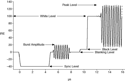
Bob, I'm having trouble making sense of this graph. I read the National Instruments page it comes from, but I'm not sure I've got it straight. See if this sounds right...
The Y axis ("IRE") is a somewhat arbitrary unit. That is, zero IRE is "usually 0V" but (by implication) it doesn't have to be. The zero-reference and blanking level in the signal is set by the "back porch" following the horizontal sync pulse, so any DC offset within reason is automatically compensated by the nature of the format. As long as the signal is pretty close to 1V pk-pk, it doesn't matter if it's centered on 0V -- or, as we're proposing, on 2.5V -- the zero point is wherever the "back porch" sits.
So, if you find a signal from your test camera that's riding somewhere between 0V and 3.3 or 5V, and we power the CD4066 from a single 5V rail, we should be in good shape.
Since the IRE scale spans -40 to +120 in the NTSC format, and an NTSC signal is supposed to be 1V pk-pk (into 75 ohms), then you could say that 1 IRE = 12.5mV.
Is that in the ballpark?
Thanks!
Eric
| | - The Matronics AeroElectric-List Email Forum - | | | Use the List Feature Navigator to browse the many List utilities available such as the Email Subscriptions page, Archive Search & Download, 7-Day Browse, Chat, FAQ, Photoshare, and much more:
http://www.matronics.com/Navigator?AeroElectric-List |
|
|
|
| Back to top |
|
 |
|
|
You cannot post new topics in this forum
You cannot reply to topics in this forum
You cannot edit your posts in this forum
You cannot delete your posts in this forum
You cannot vote in polls in this forum
You cannot attach files in this forum
You can download files in this forum
|
Powered by phpBB © 2001, 2005 phpBB Group
|


