 |
Matronics Email Lists
Web Forum Interface to the Matronics Email Lists
|
| View previous topic :: View next topic |
| Author |
Message |
jluckey(at)pacbell.net
Guest
|
 Posted: Mon Nov 13, 2023 9:50 am Post subject: Fuse Upstream of Breaker Posted: Mon Nov 13, 2023 9:50 am Post subject: Fuse Upstream of Breaker |
 |
|
Listers,


I want to put a 5 amp breaker in the regulator circuit in a airplane that has a 12-fuse distribution panel.  The breaker would be mounted in the instrument panel which is about 2-3 feet away from the fuse panel.

Can I put a big fuse, say 20 or 30A, to feed the 5A breaker?  Since breakers trip much more slowly than fuses, I'm seeking guidelines for sizing a fuse for this scenario.  (Should the up-stream fuse be 5x or 10x or ??x the breaker?)


I took a look at the Littelfuse line of MAXI fuses,  kind of a ATC slow-blow fuse, available in 20, 30, 40, 50 amps etc.

The wiring would go like this:1. Use a MAXI30 (~6x the 5 amp breaker)2. Run a #14? from the fuse to the breaker (big enough to clear a short circuit but not so big as to be un-weildy)

3. Then run a #18 from the load side of breaker to the regulator on the firewall


I am looking at BobN's analysis of a fatal accident in a Experimental with an electrically-dependent engine where the electrical system had fuses up-stream/in-series with breakers. (PDF attached)

IIRC, the system suffered a ground fault in one of the ignition modules which was supposed to be protected by a 5A circuit breaker.  The breaker is down-stream from 2 fuses.  The failure occurred because BOTH up-stream fuses blew before the 5A breaker.  I don't know what the values of the up-stream fuses were.

My case is not nearly as critical since the circuit in question only controls the regulator and the A/C does not have an electrically-dependent engine
| | - The Matronics AeroElectric-List Email Forum - | | | Use the List Feature Navigator to browse the many List utilities available such as the Email Subscriptions page, Archive Search & Download, 7-Day Browse, Chat, FAQ, Photoshare, and much more:
http://www.matronics.com/Navigator?AeroElectric-List |
|
|
|
| Back to top |
|
 |
Ceengland
Joined: 11 Oct 2020
Posts: 381
Location: MS
|
| Posted: Mon Nov 13, 2023 10:34 am Post subject: Fuse Upstream of Breaker |
|
|
On 11/13/2023 11:49 AM, Jeff Luckey wrote:
| Quote: | Listers,
I want to put a 5 amp breaker in the regulator circuit in a airplane that has a 12-fuse distribution panel. The breaker would be mounted in the instrument panel which is about 2-3 feet away from the fuse panel.
Can I put a big fuse, say 20 or 30A, to feed the 5A breaker? Since breakers trip much more slowly than fuses, I'm seeking guidelines for sizing a fuse for this scenario. (Should the up-stream fuse be 5x or 10x or ??x the breaker?)
I took a look at the Littelfuse line of MAXI fuses, kind of a ATC slow-blow fuse, available in 20, 30, 40, 50 amps etc.
The wiring would go like this:
1. Use a MAXI30 (~6x the 5 amp breaker)
2. Run a #14? from the fuse to the breaker (big enough to clear a short circuit but not so big as to be un-weildy)
3. Then run a #18 from the load side of breaker to the regulator on the firewall
I am looking at BobN's analysis of a fatal accident in a Experimental with an electrically-dependent engine where the electrical system had fuses up-stream/in-series with breakers. (PDF attached)
IIRC, the system suffered a ground fault in one of the ignition modules which was supposed to be protected by a 5A circuit breaker. The breaker is down-stream from 2 fuses. The failure occurred because BOTH up-stream fuses blew before the 5A breaker. I don't know what the values of the up-stream fuses were.
My case is not nearly as critical since the circuit in question only controls the regulator and the A/C does not have an electrically-dependent engine.
I'm willing to bench test, but since the MAXI fuses are about $6 each, testing could get a little pricey.
Seeking the Wisdom of the Crowd and TIA,
-Jeff
|
Hi Jeff,
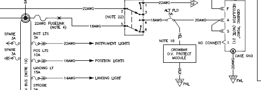
 The book describes how to protect that feeder, using a 'fusible link' that you can fabricate. The fusible link will be more reliable than any separate device, and virtually free to make. You can use 22AWG wire as the link, with one end on the supply post to the fuseblock and soldered or crimped to 18AWG wire which continues to the CB. You can sleeve the 22AWG with the fiberglass sleeving sold by B&C, or do what I did and sleeve it with regular silicone tubing. A catastrophic fault (which is what we're protecting from) will almost instantly vaporize the 22AWG, and the silicone tubing easily contains it. 'Note 4' starts on page Z-7 of the book.
[img]cid:part1.oVN4agYs.vY54mesI(at)gmail.com[/img]
 Virus-free.www.avast.com[url=#DAB4FAD8-2DD7-40BB-A1B8-4E2AA1F9FDF2] [/url] Virus-free.www.avast.com[url=#DAB4FAD8-2DD7-40BB-A1B8-4E2AA1F9FDF2] [/url]
| | - The Matronics AeroElectric-List Email Forum - | | | Use the List Feature Navigator to browse the many List utilities available such as the Email Subscriptions page, Archive Search & Download, 7-Day Browse, Chat, FAQ, Photoshare, and much more:
http://www.matronics.com/Navigator?AeroElectric-List |
|
| Description: |
|
| Filesize: |
24.59 KB |
| Viewed: |
1781 Time(s) |
|
_________________
Charlie |
|
| Back to top |
|
|
nuckolls.bob(at)aeroelect
Guest
|
| Posted: Tue Nov 14, 2023 8:59 am Post subject: Fuse Upstream of Breaker |
|
|
At 11:49 AM 11/13/2023, you wrote:
| Quote: | Listers,
I want to put a 5 amp breaker in the regulator circuit in a airplane that has a 12-fuse distribution panel. The breaker would be mounted in the instrument panel which is about 2-3 feet away from the fuse panel. |
Per Charlie's suggestion and configurations
depicted in ALL the Z-figures, fusible linked
extension of the bus to the remote breaker
is recommended.
Bob . . .
////
(o o)
===========o00o=(_)=o00o=========
< Go ahead, make my day . . . >
< show me where I'm wrong. >
=================================
In the interest of creative evolution
of the-best-we-know-how-to-do based
on physics and good practice.
| | - The Matronics AeroElectric-List Email Forum - | | | Use the List Feature Navigator to browse the many List utilities available such as the Email Subscriptions page, Archive Search & Download, 7-Day Browse, Chat, FAQ, Photoshare, and much more:
http://www.matronics.com/Navigator?AeroElectric-List |
|
|
|
| Back to top |
|
|
nuckolls.bob(at)aeroelect
Guest
|
| Posted: Tue Nov 14, 2023 9:30 am Post subject: Fuse Upstream of Breaker |
|
|
| Quote: |
I am looking at BobN's analysis of a fatal accident in a Experimental with an electrically-dependent engine where the electrical system had fuses up-stream/in-series with breakers. (PDF attached)
IIRC, the system suffered a ground fault in one of the ignition modules which was supposed to be protected by a 5A circuit breaker. The breaker is down-stream from 2 fuses. The failure occurred because BOTH up-stream fuses blew before the 5A breaker. I don't know what the values of the up-stream fuses were. |
This was not a fatal accident although very
expensive with some victims suffering enduring
effects of their injuries.
Suggest you study the analysis of that accident
more carefully. Deliverables produced for my
client in this analysis are available at:
http://aeroelectric.com/Reference_Docs/Accidents/N811HB_Feb2008_LA-IVp/
In particular, check out the demonstrated
performance of the system AS INSTALLED on
the aircraft:
http://aeroelectric.com/Reference_Docs/Accidents/N811HB_Feb2008_LA-IVp/02_N811HB_Configuration.mp4
This project was burdened with many 'slices of swiss cheese',
errors in judgement that set the stage for this accident.
The most significant features of this system were:
(1) Bus tie contactor featured in Z-14 was replaced with
a DIODE and breaker. The diode injected a fixed voltage
drop between main and aux busses of approximately
0.7 volts.
(2) For reasons not clear to me, it was deemed useful
to bring power sources for BOTH flight critical systems
TOGETHER into a single point of failure.
(3) Lack of failure mode effects analysis supported
by LOADS data for the ignition system.
The diode voltage drop and mis-configuration of
the ignition power feeders caused a single fuse
to be burdened with the draw for BOTH ignition
systems. This combined with the fact that max
draw was transient . . . take off and initial
climb-out with prop set for full increase.
These events were only once-per flight cycle
and limited to perhaps 60 seconds per event.
Not severe enough to pop the fuse on any one
event but EACH event abused the fuse causing
its I(squared)T fusing value to steadily
erode.
The main fuse went first leaving the aux fuse
to soldier on for some number of flight cycles
but it too eventually succumbed to the
abuse.
There was no gross fault condition causing the
fuses to open; rather a combination of design
decisions which produced a system that WAS
GOING TO FAIL.
Had the system been configured in the spirit
and intent of Z-14 as published,
http://aeroelectric.com/Reference_Docs/Accidents/N811HB_Feb2008_LA-IVp/04_Z14_Hypothesis.mp4
those ignition breakers and common, dual-feed
ignition bus would NOT have been installed
and just perhaps, that airplane and those people
would still be whole today.
I'll never forget my first view of the sketches
for the system as-installed on HB811. My
client spread them out on his desk and I
could see immediately why this engine quit
on 'short final to the rocks'.
Bob . . .
////
(o o)
===========o00o=(_)=o00o=========
< Go ahead, make my day . . . >
< show me where I'm wrong. >
=================================
In the interest of creative evolution
of the-best-we-know-how-to-do based
on physics and good practice.
| | - The Matronics AeroElectric-List Email Forum - | | | Use the List Feature Navigator to browse the many List utilities available such as the Email Subscriptions page, Archive Search & Download, 7-Day Browse, Chat, FAQ, Photoshare, and much more:
http://www.matronics.com/Navigator?AeroElectric-List |
|
|
|
| Back to top |
|
|
nuckolls.bob(at)aeroelect
Guest
|
| Posted: Tue Nov 14, 2023 1:09 pm Post subject: Fuse Upstream of Breaker |
|
|
| Quote: | The main fuse went first leaving the aux fuse
to soldier on for some number of flight cycles
but it too eventually succumbed to the
abuse. |
This is what FMEA is all about. Here was an
opportunity for a latent failure to go
un-annunciated and impossible to
detect in a pre-flight procedure. Interestingly
also, even if the fuses had been fitted with
LED indicators, it is unlikely that the
failed fuse would have 'indicated' anything.
Voltage across open fuse too low.
Bob . . .
////
(o o)
===========o00o=(_)=o00o=========
< Go ahead, make my day . . . >
< show me where I'm wrong. >
=================================
In the interest of creative evolution
of the-best-we-know-how-to-do based
on physics and good practice.
| | - The Matronics AeroElectric-List Email Forum - | | | Use the List Feature Navigator to browse the many List utilities available such as the Email Subscriptions page, Archive Search & Download, 7-Day Browse, Chat, FAQ, Photoshare, and much more:
http://www.matronics.com/Navigator?AeroElectric-List |
|
|
|
| Back to top |
|
|
jluckey(at)pacbell.net
Guest
|
| Posted: Fri Nov 17, 2023 11:05 am Post subject: Fuse Upstream of Breaker |
|
|
Re Bob's Accident Analysis:
I stand corrected. My recollection was a little faulty. (no big surprise)
This case is fascinating to me. It appears to be a classic case of "over-engineering". The designer(s) were trying to be uber-redundant and in so doing they, shall we say, "screwed the pooch". I'm glad to be reminded that it was not fatal.
Please understand that my intent is not to criticize the people involved but to learn how not to make the same mistake. (And I have to say, kudos to BobN for fostering and promoting that philosophy here on the List)
So Bob, after watching some of your videos, I don't recall what size fuse was used in the upstream position. Was it 5A, same as the breakers?
Experiments from "The Lab":
I did some experimentation and found that a fuse upstream of a breaker needs to be at least 4x the breaker rating. I put a 30A fuse upstream from a 5A breaker and the fuse held, and the breaker popped. (yes, that is 6x, but I didn't have any 20A fuses). I performed the test at least 10 times.
Also tested with 10A breaker. First, with a 30A fuse which blew instantly. Then with a 40A fuse which held and the 10A breaker popped, again 10 cycles. (hence the 4x)
Sometimes I would have to wait 10 to 30 seconds before the breaker would reset. Ambient temp was 68F.
My setup:
I was using a freshly-charged PC-680, about 3 feet of 18 AWG wire, a mil-spec SPST toggle switch (cuz that's what I had lying around), ATO automotive fuses and connecting to them using individual .250 tab connectors.
Observational Note:
I was surprised at how big the "pop" was in the 30A fuse when testing the 10A breaker. There was a clearly audible "snap" or "pop" and a bright flash as the fuse element burned. I thought it would just quietly melt. The circuit breakers were: 10A WX23 series (push-pull) and a WX58 5A (push to reset).
I like the fuse for this because:
1. It just uses a regular slot in the fuse block
2. It uses a stock, cheap fuse
3. It's easy to replace
4. There are no lengths of #22 being vaporized at high temps
5. The fuse element is encapsulated in an enclosure that is designed to contain its melt-down. (you know, It's a fuse;)
People have suggested that the "recommended" solution for this scenario is a fusible link. Why is a fusible link better than a 4x fuse under these relatively low-current situations?
Inquiring minds....
-Jeff
On Tuesday, November 14, 2023 at 01:15:32 PM PST, Robert L. Nuckolls, III <nuckolls.bob(at)aeroelectric.com> wrote:
| Quote: | The main fuse went first leaving the aux fuse
to soldier on for some number of flight cycles
but it too eventually succumbed to the
abuse. |
This is what FMEA is all about. Here was an
opportunity for a latent failure to go
un-annunciated and impossible to
detect in a pre-flight procedure. Interestingly
also, even if the fuses had been fitted with
LED indicators, it is unlikely that the
failed fuse would have 'indicated' anything.
Voltage across open fuse too low.
Bob . . .
////
(o o)
===========o00o=(_)=o00o=========
< Go ahead, make my day . . . >
< show me where I'm wrong. >
=================================
In the interest of creative evolution
of the-best-we-know-how-to-do based
on physics and good practice.
| | - The Matronics AeroElectric-List Email Forum - | | | Use the List Feature Navigator to browse the many List utilities available such as the Email Subscriptions page, Archive Search & Download, 7-Day Browse, Chat, FAQ, Photoshare, and much more:
http://www.matronics.com/Navigator?AeroElectric-List |
|
|
|
| Back to top |
|
|
Ceengland
Joined: 11 Oct 2020
Posts: 381
Location: MS
|
| Posted: Fri Nov 17, 2023 3:31 pm Post subject: Fuse Upstream of Breaker |
|
|
snipped | Quote: |
People have suggested that the "recommended" solution for this scenario is a fusible link. Why is a fusible link better than a 4x fuse under these relatively low-current situations?
Inquiring minds....
-Jeff
|
I like them because once they're fab'd, they're zero maintenance and virtually zero risk of failure/nuisance trip, and there are fewer failure points because there are fewer joints in the path. Any fault severe enough to 'trip' the link is going to make a far larger arc, and noise, and smoke puff, than the link itself will make. It's simple and cheap to test; that's what I did to verify the safety/effectiveness of using silicone tubing for the protective layer over the link.
Virus-free.www.avast.com[url=#DAB4FAD8-2DD7-40BB-A1B8-4E2AA1F9FDF2] [/url]
| | - The Matronics AeroElectric-List Email Forum - | | | Use the List Feature Navigator to browse the many List utilities available such as the Email Subscriptions page, Archive Search & Download, 7-Day Browse, Chat, FAQ, Photoshare, and much more:
http://www.matronics.com/Navigator?AeroElectric-List |
|
_________________
Charlie |
|
| Back to top |
|
|
nuckolls.bob(at)aeroelect
Guest
|
| Posted: Fri Nov 17, 2023 4:00 pm Post subject: Fuse Upstream of Breaker |
|
|
At 05:36 PM 11/17/2023, you wrote:
| Quote: | snipped
| Quote: |
People have suggested that the "recommended" solution for this
scenario is a fusible link. Why is a fusible link better than a 4x fuse under these relatively low-current situations?
|
|
The fusible link is close cousin to the
ANL/MANL/MIDI current limiters. Much more
robust than a fuse but STILL quite capable
of protecting a feeder suffering a hard-fault.
That short chunk of wire from main bus to
the alternator field crowbar breaker is
an EXTENSION of the main bus. Protection
on a bus extension is tailored to protect
the conductor but expected to source one
or more, smaller feeders for ship's
accessories. The I(squared)T value for
the link is several times larger than
any downstream breaker/fuse.
Some of my builders have used this extension
to source a crowbar field breaker -and- supply
breaker to the autopilot. This was to provide
a means for disabling the a/p should it become
fussy. One might find it useful to source other
breakers in an otherwise all-fuse airplane. In
this case, the extension might be upsized to
12AWG with a 16AWG fusible link.
It's a reliable, simpler, low parts count way
to extend the bus without 'wasting' a slot in your
fuseholder.
Bob . . .
////
(o o)
===========o00o=(_)=o00o=========
< Go ahead, make my day . . . >
< show me where I'm wrong. >
=================================
In the interest of creative evolution
of the-best-we-know-how-to-do based
on physics and good practice.
| | - The Matronics AeroElectric-List Email Forum - | | | Use the List Feature Navigator to browse the many List utilities available such as the Email Subscriptions page, Archive Search & Download, 7-Day Browse, Chat, FAQ, Photoshare, and much more:
http://www.matronics.com/Navigator?AeroElectric-List |
|
|
|
| Back to top |
|
|
|
|
You cannot post new topics in this forum
You cannot reply to topics in this forum
You cannot edit your posts in this forum
You cannot delete your posts in this forum
You cannot vote in polls in this forum
You cannot attach files in this forum
You can download files in this forum
|
Powered by phpBB © 2001, 2005 phpBB Group
|

