 |
Matronics Email Lists
Web Forum Interface to the Matronics Email Lists
|
| View previous topic :: View next topic |
| Author |
Message |
jluckey(at)pacbell.net
Guest
|
 Posted: Fri Nov 10, 2023 8:39 am Post subject: RF Antenna Help Posted: Fri Nov 10, 2023 8:39 am Post subject: RF Antenna Help |
 |
|
Don,

Your explanation helps me understand some of the practical considerations with respect to coax antenna lines.  Thank you. (RF has always been kind of a mysterious subject for me)

Next question:


As you can see from the photos, the center conductor is un-insulated and if I install the C-ring, they will touch - that would be bad.  Can I install a very short length of the center conductor insulation over that exposed center conductor?

I'm thinking that I could cut a ~3/16" piece of insulation (from the core of a length of RG-400), cut a slit in it axially, and press it over the exposed center conductor.  And then, to keep it from possibly slipping off due to vibration (I don't think it will, but just to be safe), can a put a drop of CA super glue on it?  Would that work?

TIA

-Jeff


                                                                    On Friday, November 10, 2023 at 08:19:11 AM PST, Don Pansier <dpansier1(at)new.rr.com> wrote:


                 The C shaped device is there to prevent an Impedance Bump. Impedance Bumps can cause high VSWR, weak return loss, and poor system performance.


Coaxial transmission lines rely on a ratio between the diameter of the center conductor and the ID of the outer conductor, in this case the ratio is sized for 50 ohms impedance.


Due to size limitations of the connector, it would be very difficult to make the connection from the coax to the center pin of the connector without a removable section. Reinstalling the C shaped section returns the transmission line back to the correct ratio.


Impedance Bumps in Coaxial cables can also be caused by pinching, crushing and bending beyond the min radius,  all changing the ratio between the ID and the OD of the transmission line.
| | - The Matronics AeroElectric-List Email Forum - | | | Use the List Feature Navigator to browse the many List utilities available such as the Email Subscriptions page, Archive Search & Download, 7-Day Browse, Chat, FAQ, Photoshare, and much more:
http://www.matronics.com/Navigator?AeroElectric-List |
|
|
|
| Back to top |
|
 |
nuckolls.bob(at)aeroelect
Guest
|
| Posted: Sat Nov 11, 2023 7:58 am Post subject: RF Antenna Help |
|
|
At 10:38 AM 11/10/2023, you wrote:
| Quote: | Don,
Your explanation helps me understand some of the practical considerations with respect to coax antenna lines. Thank you. (RF has always been kind of a mysterious subject for me)
Next question:
As you can see from the photos, the center conductor is un-insulated and if I install the C-ring, they will touch - that would be bad. Can I install a very short length of the center conductor insulation over that exposed center conductor?
I'm thinking that I could cut a ~3/16" piece of insulation (from the core of a length of RG-400), cut a slit in it axially, and press it over the exposed center conductor. And then, to keep it from possibly slipping off due to vibration (I don't think it will, but just to be safe), can a put a drop of CA super glue on it? Would that work?
TIA
-Jeff
On Friday, November 10, 2023 at 08:19:11 AM PST, Don Pansier <dpansier1(at)new.rr.com> wrote:
The C shaped device is there to prevent an Impedance Bump. Impedance Bumps can cause high VSWR, weak return loss, and poor system performance.
Coaxial transmission lines rely on a ratio between the diameter of the center conductor and the ID of the outer conductor, in this case the ratio is sized for 50 ohms impedance.
Due to size limitations of the connector, it would be very difficult to make the connection from the coax to the center pin of the connector without a removable section. Reinstalling the C shaped section returns the transmission line back to the correct ratio.
Impedance Bumps in Coaxial cables can also be caused by pinching, crushing and bending beyond the min radius, all changing the ratio between the ID and the OD of the transmission line. |
Yeahhhh . . . sort of. The practical effects of 'bumps', 'kinks'
and sharp bends in perhaps 20' of coax are worries only
an academic could appreciate. These are things easily detected
and measured in a lab with sophisticated equipment.
But can one demonstrate effects of these anomalies while cruising
at 10K in your RV? Not so much.
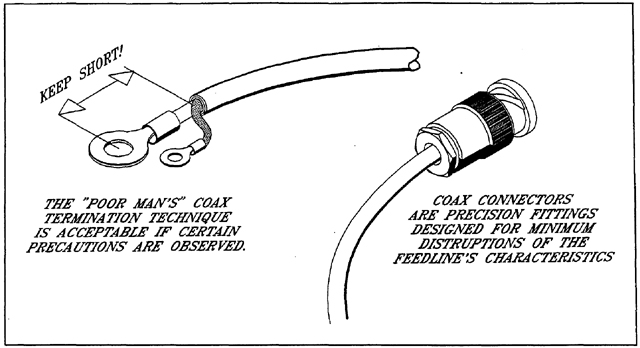
Consider the attached drawings that illustrate variations in
coax cable terminations. In Figure 1, we see two techniques
commonly found in countless production aircraft. (a) crimp
some terminals on the ends of the conductors and (b) install
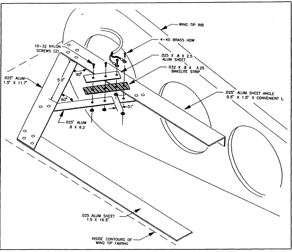
a righteous coax connector. In Figure 2 we see one of Bob
Archer's famous, wing-tip VOR antennas tailored to RV
aircraft. Note that it features crude coax termination as in 1(A).
However, Bob's design also features a matching section
intended to optimize impedance matching between the antenna
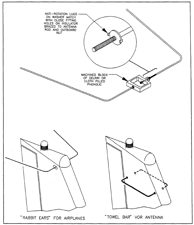
and feedline. In Figure 3, we see a VOR antenna that was used
on hundreds of thousands of aircraft for decades. It too uses
terminals-on-conductors ('bumpy') and no attempt to optimize
impedance matching or correct for conditions posed by
connecting an 'unbalanced' feedline (coax) directly to
a 'balanced' antenna (dipole).
Hmmmm . . . if one scans these two antennas with a network
analyzer or time domain reflectometer, I suspect that the
Archer antenna would present 'nicer' characteristics
than the legacy 'rabbit ears' used for a century or so.
However, in terms of practical performance, it would not
surprise me to discover that the whiskers outperform
the wing-tip antenna in terms of receiver sensitivity
as measured in a circle around the airplane.
Now, does that bode ill for Mr. Archer's brainchild?
I suspect not . . . there are many examples flying
today. We're not hearing/reading of operator-owners
replacing them with 'something better'.
I cite this as one of countless examples of variations
in performance among similar systems. The market-place
question is, does Bob's antenna perform adequately to
the pilot's needs? The answer to that must be 'yes'.
This in spite of theoretical anomalies (like a 'bumpy'
coax termination) having no demonstrable shortcoming in practice.
The little c-ring under discussion in this thread
is one such example. Your market-place question is,
'would I KNOW that it were or were not present by
observing stuff on my panel? You've noticed that it might
prove unhandy should it not hold proper position
within the connector and cause a short.
I'd pitch the thing and not give it another thought.
Bob . . .
////
(o o)
===========o00o=(_)=o00o=========
< Go ahead, make my day . . . >
< show me where I'm wrong. >
=================================
In the interest of creative evolution
of the-best-we-know-how-to-do based
on physics and good practice.
| | - The Matronics AeroElectric-List Email Forum - | | | Use the List Feature Navigator to browse the many List utilities available such as the Email Subscriptions page, Archive Search & Download, 7-Day Browse, Chat, FAQ, Photoshare, and much more:
http://www.matronics.com/Navigator?AeroElectric-List |
|
| Description: |
|
| Filesize: |
77.75 KB |
| Viewed: |
1577 Time(s) |
|
| Description: |
|
| Filesize: |
203.6 KB |
| Viewed: |
1577 Time(s) |
|
| Description: |
|
| Filesize: |
123.44 KB |
| Viewed: |
1577 Time(s) |
|
|
|
| Back to top |
|
|
jluckey(at)pacbell.net
Guest
|
| Posted: Sun Nov 12, 2023 8:54 am Post subject: RF Antenna Help |
|
|
Thanks Bob for taking the time to explain and to Don also...
I ended up doing as I described in my previous post and it seems satisfactory. (I did that work before seeing BobN's post)
I have not transmitted with the radio yet. That will come next week.
On Saturday, November 11, 2023 at 08:07:42 AM PST, Robert L. Nuckolls, III <nuckolls.bob(at)aeroelectric.com> wrote:
At 10:38 AM 11/10/2023, you wrote: | Quote: | | Don, Your explanation helps me understand some of the practical considerations with respect to coax antenna lines. Thank you. (RF has always been kind of a mysterious subject for me) Next question: As you can see from the photos, the center conductor is un-insulated and if I install the C-ring, they will touch - that would be bad. Can I install a very short length of the center conductor insulation over that exposed center conductor? I'm thinking that I could cut a ~3/16" piece of insulation (from the core of a length of RG-400), cut a slit in it axially, and press it over the exposed center conductor. And then, to keep it from possibly slipping off due to vibration (I don't think it will, but just to be safe), can a put a drop of CA super glue on it? Would that work? TIA -Jeff On Friday, November 10, 2023 at 08:19:11 AM PST, Don Pansier <dpansier1(at)new.rr.com> wrote: The C shaped device is there to prevent an Impedance Bump. Impedance Bumps can cause high VSWR, weak return loss, and poor system performance. Coaxial transmission lines rely on a ratio between the diameter of the center conductor and the ID of the outer conductor, in this case the ratio is sized for 50 ohms impedance. Due to size limitations of the connector, it would be very difficult to make the connection from the coax to the center pin of the connector without a removable section. Reinstalling the C shaped section returns the transmission line back to the correct ratio. Impedance Bumps in Coaxial cables can also be caused by pinching, crushing and bending beyond the min radius, all changing the ratio between the ID and the OD of the transmission line. |
Yeahhhh . . . sort of. The practical effects of 'bumps', 'kinks' and sharp bends in perhaps 20' of coax are worries only an academic could appreciate. These are things easily detected and measured in a lab with sophisticated equipment. But can one demonstrate effects of these anomalies while cruising at 10K in your RV? Not so much. Consider the attached drawings that illustrate variations in coax cable terminations. In Figure 1, we see two techniques commonly found in countless production aircraft. (a) crimp some terminals on the ends of the conductors and (b) install a righteous coax connector. In Figure 2 we see one of Bob Archer's famous, wing-tip VOR antennas tailored to RV aircraft. Note that it features crude coax termination as in 1(A). However, Bob's design also features a matching section intended to optimize impedance matching between the antenna and feedline. In Figure 3, we see a VOR antenna that was used on hundreds of thousands of aircraft for decades. It too uses terminals-on-conductors ('bumpy') and no attempt to optimize impedance matching or correct for conditions posed by connecting an 'unbalanced' feedline (coax) directly to a 'balanced' antenna (dipole). Hmmmm . . . if one scans these two antennas with a network analyzer or time domain reflectometer, I suspect that the Archer antenna would present 'nicer' characteristics than the legacy 'rabbit ears' used for a century or so. However, in terms of practical performance, it would not surprise me to discover that the whiskers outperform the wing-tip antenna in terms of receiver sensitivity as measured in a circle around the airplane. Now, does that bode ill for Mr. Archer's brainchild? I suspect not . . . there are many examples flying today. We're not hearing/reading of operator-owners replacing them with 'something better'. I cite this as one of countless examples of variations in performance among similar systems. The market-place question is, does Bob's antenna perform adequately to the pilot's needs? The answer to that must be 'yes'. This in spite of theoretical anomalies (like a 'bumpy' coax termination) having no demonstrable shortcoming in practice. The little c-ring under discussion in this thread is one such example. Your market-place question is, 'would I KNOW that it were or were not present by observing stuff on my panel? You've noticed that it might prove unhandy should it not hold proper position within the connector and cause a short. I'd pitch the thing and not give it another thought.
Bob . . . //// (o o) ===========o00o=(_)=o00o========= < Go ahead, make my day . . . > < show me where I'm wrong. > ================================= In the interest of creative evolution of the-best-we-know-how-to-do based on physics and good practice.
| | - The Matronics AeroElectric-List Email Forum - | | | Use the List Feature Navigator to browse the many List utilities available such as the Email Subscriptions page, Archive Search & Download, 7-Day Browse, Chat, FAQ, Photoshare, and much more:
http://www.matronics.com/Navigator?AeroElectric-List |
|
|
|
| Back to top |
|
|
|
|
You cannot post new topics in this forum
You cannot reply to topics in this forum
You cannot edit your posts in this forum
You cannot delete your posts in this forum
You cannot vote in polls in this forum
You cannot attach files in this forum
You can download files in this forum
|
Powered by phpBB © 2001, 2005 phpBB Group
|

