 |
Matronics Email Lists
Web Forum Interface to the Matronics Email Lists
|
| View previous topic :: View next topic |
| Author |
Message |
user9253
Joined: 28 Mar 2008
Posts: 1908
Location: Riley TWP Michigan
|
 Posted: Wed Sep 27, 2023 6:23 pm Post subject: Re: OVM14 MkIII, rev P1 Posted: Wed Sep 27, 2023 6:23 pm Post subject: Re: OVM14 MkIII, rev P1 |
 |
|
Thanks Eric for explaining how the LM293 works. I had it all wrong.
| | - The Matronics AeroElectric-List Email Forum - | | | Use the List Feature Navigator to browse the many List utilities available such as the Email Subscriptions page, Archive Search & Download, 7-Day Browse, Chat, FAQ, Photoshare, and much more:
http://www.matronics.com/Navigator?AeroElectric-List |
|
_________________
Joe Gores |
|
| Back to top |
|
 |
user9253
Joined: 28 Mar 2008
Posts: 1908
Location: Riley TWP Michigan
|
| Posted: Thu Sep 28, 2023 9:31 am Post subject: Re: OVM14 MkIII, rev P1 |
|
|
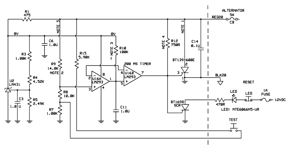
A wise man once said, "That popped circuit breaker just prevented a fire.

Do you want to reset it and give the fire a second chance?"

Adding a 50 cent TO-92 part and a LED could save much time troubleshooting the cause of the tripped breaker.

More importantly, if the LED is illuminated, the pilot will know that it is safe to reset the breaker.

If the LED is off, then it is best to wait until safely on the ground before resetting the breaker.

The suggested LED has a narrow beam angle and should be aimed toward the pilot's face.

I modified Bob N's circuit below by adding an SCR and external LED circuit.  And thanks Eric for your help.
| | - The Matronics AeroElectric-List Email Forum - | | | Use the List Feature Navigator to browse the many List utilities available such as the Email Subscriptions page, Archive Search & Download, 7-Day Browse, Chat, FAQ, Photoshare, and much more:
http://www.matronics.com/Navigator?AeroElectric-List |
|
| Description: |
|
| Filesize: |
54.03 KB |
| Viewed: |
16692 Time(s) |
|
_________________
Joe Gores |
|
| Back to top |
|
|
nuckolls.bob(at)aeroelect
Guest
|
| Posted: Sat Sep 30, 2023 5:24 pm Post subject: OVM14 MkIII, rev P1 |
|
|
At 12:31 PM 9/28/2023, you wrote:
| Quote: | --> AeroElectric-List message posted by: "user9253" <fransew(at)gmail.com>
A wise man once said, "That popped circuit breaker just prevented a fire.
Do you want to reset it and give the fire a second chance?" |
There's a not so subtle difference in stresses
that pop breakers. Assuming the breaker was indeed
opened by an ov event, then the breaker was responding
to an artificially created, dead-short by means of
an electronic short to ground. The breaker opens in
typically 15-30 milliseconds.
The potentially hazardous fault is generally
a soft fault that takes a long time to open
the breaker if ever.
Recall the story about the Model 99 Beech
on short final to runway in New Mexico suddenly
experiencing total disconnect between the wheel
and elevators. Seem a 6AWG feeder to windshield
de-ice system (protected by a 60A breaker) had
be badly positioned during maintenance under
the copilot's floorboards. It was rubbing against
the elevator cable for many weeks after the
maintenance action. Insulation eventually wore
away and the cable began to arc against the
exposed wire. No smoke, no fire, no visible
anomalies in the cockpit. But the relative
robustness of copper vs. steel was demonstrated
when the control cable finally parted.
The ship was successfully landed using elevator
trim. Damage to the wire itself was minimal . . .
stainless steel control cable not so fortunate.
That scenario offered a great deal more potential
for causing a fire WITHOUT opening a breaker
than a hard fault that would open a breaker
almost instantly.
The rational for specifying a high quality,
aircraft friendly breaker as upstream CBOVM
systems was allow, nay encourage a reset-it-once
action by the pilot. This allows the pilot
to deduce if the ov trip was a nuisance event
or a real one. If it were a nuisance event,
the breaker would stay in, the alternator would
come back on line and the bus voltage would be
normal.
Should this prove to be a repeating even over
a period of time, an investigation into root
cause is indicted . . . and not easy. I've had
occasion to chase down two such events; one on
a Europa and the other on a Beechjet. The first
one was fairly easy, the last one cost mucho
Kilobux before root cause was located and
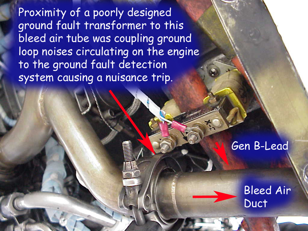
remedied. After more than a month of diligent
attention from field service, I instrumented
the fault detection circuitry in the generator
control unit and conducted a bunch of tests
that eventually pointed to the ground fault
transformer as the source of the antagonistic
signal. The signal cropped up on this aging
airplane as ever increasing ground path
resistance rose with time. Built a sheet metal
bracket to relocate the transformer 1 inch further
away and the noise disappeared!
The point being that the first trip signals
potential for an enduring problem in which case,
resetting the breaker simply forces the OV
management system to do an encore and
the breaker quickly reopens. Once determined that
multiple resets in support of testing does
not constitute a hazard, multiple 'trips'
while probing the system is not contraindicated.
This was a particularly miserable job . . .
had to bring the airplane into a hangar to
configure various tests and then taxi it out
to the compass rose about 1/2 mile way
in freezing rain to conduct the tests!
| Quote: | Adding a 50 cent TO-92 part and a LED could save much time troubleshooting the cause of the tripped breaker.
More importantly, if the LED is illuminated, the pilot will know that it is safe to reset the breaker.
If the LED is off, then it is best to wait until safely on the ground before resetting the breaker.
The suggested LED has a narrow beam angle and should be aimed toward the pilot's face.
I modified Bob N's circuit below by adding an SCR and external LED circuit. And thanks Eric for your help. |
There's nothing bad about the proposed ov
trip memory light but I suggest it has
no practical value. 99.99% of all breakers
and fuses go to the bone yard never having been
called upon to prevent a fault from maturing to
a hazardous condition. Even the ATP category
operations manuals allow for reset-one-time for critical
systems. One is not flirting with disaster
by asking the system to confirm a condition while
observing results of a well crafted and monitored
test. I'll be we 'tripped' that Beechjet 20+ times
before we found the problem.
I can assure you that when and if that breaker
opens, lo volts warning will tell you about
it very quickly and the fault is almost certainly
a perceived ov condition. The current re-design (longer
and self re-setting time delay) promises
to reduce probably of nuisance trips
to 10 to the minus 9 probability numbers.
Bob . . .
////
(o o)
===========o00o=(_)=o00o=========
< Go ahead, make my day . . . >
< show me where I'm wrong. >
=================================
In the interest of creative evolution
of the-best-we-know-how-to-do based
on physics and good practice.
| | - The Matronics AeroElectric-List Email Forum - | | | Use the List Feature Navigator to browse the many List utilities available such as the Email Subscriptions page, Archive Search & Download, 7-Day Browse, Chat, FAQ, Photoshare, and much more:
http://www.matronics.com/Navigator?AeroElectric-List |
|
| Description: |
|
| Filesize: |
429.26 KB |
| Viewed: |
16674 Time(s) |
|
| Description: |
|
| Filesize: |
468.02 KB |
| Viewed: |
16674 Time(s) |
|
|
|
| Back to top |
|
|
user9253
Joined: 28 Mar 2008
Posts: 1908
Location: Riley TWP Michigan
|
| Posted: Sun Oct 01, 2023 10:42 am Post subject: Re: OVM14 MkIII, rev P1 |
|
|
Bob, I can't argue with your logic.  However, airplanes are toys for many of

us.  And builders like to equip their toys with more toys.  Take for instance

the VP-X Electronic Circuit Breaker System.  It has lots of nice features.  But a

builder could install fuses for much less money than the sales tax on the VP-X.

Even so, many builders elect to install the VP-X because they want the

extra features.  It is the same with the over-voltage module.  Some pilots

want the extra feature of an over-voltage indicator light.  Others might elect

to not install the light or reset button.  Why not leave it up to the builder to

install what she wants?
| | - The Matronics AeroElectric-List Email Forum - | | | Use the List Feature Navigator to browse the many List utilities available such as the Email Subscriptions page, Archive Search & Download, 7-Day Browse, Chat, FAQ, Photoshare, and much more:
http://www.matronics.com/Navigator?AeroElectric-List |
|
_________________
Joe Gores |
|
| Back to top |
|
|
nuckolls.bob(at)aeroelect
Guest
|
| Posted: Mon Oct 02, 2023 9:02 pm Post subject: OVM14 MkIII, rev P1 |
|
|
Eric: My 2nd question is resolved by Rev P3 but I'm still curious about questions 1, 3 and 4.
Ach!!! Sorry 'bout that!
At 02:50 PM 9/22/2023, you wrote:
| Quote: | --> AeroElectric-List message posted by: "Eric Page" <edpav8r(at)yahoo.com>
A few things that I noticed...
1. Absolute maximum cathode-to-anode voltage on the LM431 is 37V (see TI and onsemi datasheets). A significant OV event could exceed that limit until the crowbar brings bus voltage under control. This might not be an issue with a lead-acid battery, but the OV behavior of the BMS in lithium batteries is unknown. If a lithium BMS disconnects pronto, bus voltage could rise farther and more quickly than with lead-acid on the job.
Q: Should there be a 33V Zener in parallel to protect the LM431? |
The LM431 IS a zener. It's biased up thru
392 ohm R1. So the 10V Vcc rail is rigid.
If anything is at-risk from a bus voltage
excursion, it's probably R1.
| Quote: | -----
2. The recommended maximum voltage on LM293 inputs is Vcc minus 2V (see table 6.2 in the TI datasheet). In this case Vcc is 8V, so the max input voltage is 6V.
- The 7V reference exceeds 6V on the inverting inputs of both comparators.
- Any bus voltage >13.64V will exceed 6V on the non-inverting input of U16A.
- Timing capacitor C11 on the non-inverting input of U16B will charge to 8V. |
Yeah, raised Vcc to 10V. Changed trip reference to 2.5V.
The Non inverting input to U16B will not exceed 8V 'cause
that's where the SCR trips.
| Quote: | | Q: Should the comparator reference be adjusted downward (perhaps delete R4, adjust R3/R5, and use the LM431's 2.5V reference for the comparators)? |
Yup.
| Quote: | Q: Should the non-inverting inputs be protected with 5.1V Zeners?
|
Nope . . .
| Quote: | -----
3. In recent discussion of the OVM task you mentioned your intent to make the trip delay 500mS +/- 50mS. This schematic provides ~200mS.
Q: Have you reconsidered the 500mS trip delay? |
Not necessarily. Legacy OVM management devices were oblivious
to the 20V for 1 second qualification requirements under DO160.
Powers that be were fond of the 50mS value for step response from
14.2 to 20V. I think I mentioned having offered a very
similar configuration and running the delay out further.
Early days solid-state latches for OV management were plagued
with nuisance trips very short, low energy noises on the
bus that would do a dv/dt trigger of the scr. Ultimately
managed with the 0.1 uF cap right across the SCR combined
with low value resistor gate to cathode (which drives
up required trigger current).
This design now ties the gate to ground through the open
collector output of U11B. I'm anticipating dv/dt issues
to be irrelevant.
AS to selection of time delay certainly much longer than
50mS and much smaller than 1 second. 500mS seems like a
happy medium but given the self-resetting nature of the
comparator/timer, 200mS is probably comfortable too. Either
value honors design guidance of DO160/Mil-Std-704
The current proposal offers a way to select ov trip,
maintenance trip and trip delay values with a simple
adjustment of resistors.
| Quote: | -----
4. Schematic Note 1 contemplates a crowbar current of 100-200A DC for 25mS. The BT139-600E SCR datasheet shows a peak non-repetitive on-state current of 155A, but that specification assumes an initial junction temperature of 25degC (unlikely under an engine cowling), a pulse duration â¤20mS and a full-sine-wave AC pulse, not DC. |
Those have been proven conservative . . . especially
in later years of SCR offerings. Beech had a qualification
requirement to effect 50 shutdowns in a row, each
about 2 seconds apart, with the 51st still in spec.
That protocol arose from the fact that the weakest
link in contemporary ov RELAY designs was relay
CONTACTS failing to break the inductively stabilized
ARC. Powers that be assumed that no airplane would
every experience 50 OV events, hence the BIG HAMMER
test.
It was during development of the prototype Beech Lightning
(single engine turboprop) that not a single OV relay
in Beech inventory would pass the test including those
we sold at Electo-Mech. When Jack Thurman called
to tell me the sad story, I told him I'd be in his
office in an hour.
I modified one of our stock regulator/ov relay
products to a CrowbarSCR configuration and took
it out to try on the bench test. When Jack hit
the OV initiate button, he thought something was
broke. No squawks from the alternator, no great flashing
of panel lights. The chart recorder showed a rather
un-impressive rise to 32 volts whereupon the system
was quietly shut down.
"Yeah says Jack, will it do it 50 times?"
"You bet says I".
The previously stressed devices was a relay trying
to break an inductively driven ARC. Now, major stress
was on a circuit breaker qualified for thousands of
operations doing the job it was designed for . . .
clear a faulted feeder.
Had the Lightning project continued to production,
I have no doubt that the crowbar ov management system
would see it's first application in a TC aircraft.
Unfortunately, volume production of crowbar ov
management had to wait until it appeared in the
B&C LR series regulators which eventually made
it onto TC aircraft. Lamar, PlanePower and others
picked up on the idea . . . tens of thousands of crowbar
ov sytems are flying today.
Indeed, the 50x tests were no problem. Only time
we lost SCRs was when someone tried to crowbar
a fatter breaker . . . or one with a particularly
long operate time. Typically, our favorite style
of miniature breaker opens in 25mS or less.
| Quote: | | Q: Can the BT139-600E handle this crowbar task? If not, could you swap U16B's inputs and interpose a P-FET to trigger a beefier SCR? |
Don't think this will be necessary. All of our OVM-14
versions used SCR's with rather benign single cycle
ratings. But just for grins and in honor of Jack Thurman's
skeptical testing protocols, I'll do the 50x test at 100A.
I'll go rescue my environmental chamber from a
lab in Wichita so I can test it at temperature . . .
say -20 to +150F.
Bob . . .
////
(o o)
===========o00o=(_)=o00o=========
< Go ahead, make my day . . . >
< show me where I'm wrong. >
=================================
In the interest of creative evolution
of the-best-we-know-how-to-do based
on physics and good practice.
| | - The Matronics AeroElectric-List Email Forum - | | | Use the List Feature Navigator to browse the many List utilities available such as the Email Subscriptions page, Archive Search & Download, 7-Day Browse, Chat, FAQ, Photoshare, and much more:
http://www.matronics.com/Navigator?AeroElectric-List |
|
|
|
| Back to top |
|
|
Eric Page
Joined: 15 Feb 2017
Posts: 243
|
| Posted: Tue Oct 03, 2023 12:39 pm Post subject: Re: OVM14 MkIII, rev P1 |
|
|
Wow! Thanks, Bob. That was WAY more than I expected. Sometimes
I feel like I should be making student loan payments for what I learn
on this forum.
| nuckolls.bob(at)aeroelect wrote: | The LM431 IS a zener. It's biased up thru 392 ohm R1. So the 10V
Vcc rail is rigid. If anything is at-risk from a bus voltage excursion,
it's probably R1. |
Ugh. That's pretty obvious when I read it and look at the schematic again.
More learning...
| Quote: | The Non inverting input to U16B will not exceed 8V 'cause that's where
the SCR trips. |
After reading the datasheet again, I can see that protecting the non-inverting
inputs is a non-issue. The Vcc-2V figure is an operating recommendation; the
absolute maximum is 38V. In the case of your P3 schematic, it would take 247V
on the bus to exceed that limit on U16A!
| Quote: | AS to selection of time delay certainly much longer than 50mS and much
smaller than 1 second. 500mS seems like a happy medium but given the
self-resetting nature of the comparator/timer, 200mS is probably comfortable
too. Either value honors design guidance of DO160/Mil-Std-704.
The current proposal offers a way to select ov trip, maintenance trip and trip
delay values with a simple adjustment of resistors. |
Got it. Exact delay value is unimportant, as long as it responds fast enough to
protect and slow enough to avoid nuisance trips.
| Quote: | ...the weakest link in contemporary ov RELAY designs was relay CONTACTS
failing to break the inductively stabilized ARC. |
OK, here's where I have another question. My application for OV protection is on
a Rotax 912iS, which has a built-in 450W 3-phase PM stator. Since I can't corral
a stator by blowing a breaker, I'm adapting your design to drive relays.
I've chosen an automotive relay with integral coil-suppression diode and contacts
rated for 75VDC at 40A:
https://www.digikey.com/short/n8qhp98t
Do you think that relay is likely to have any trouble breaking each leg of the
Rotax stator feed? I'm guessing not since it's an AC circuit, but guessing has
a poor track record...
-Eric
| | - The Matronics AeroElectric-List Email Forum - | | | Use the List Feature Navigator to browse the many List utilities available such as the Email Subscriptions page, Archive Search & Download, 7-Day Browse, Chat, FAQ, Photoshare, and much more:
http://www.matronics.com/Navigator?AeroElectric-List |
|
|
|
| Back to top |
|
|
user9253
Joined: 28 Mar 2008
Posts: 1908
Location: Riley TWP Michigan
|
| Posted: Tue Oct 03, 2023 4:57 pm Post subject: Re: OVM14 MkIII, rev P1 |
|
|
Eric, be sure to clearly mark the positive relay coil terminal so that you don't

mistake the same mistake that I made.  The Rotax 912iS fuse box also has

relays with internal diodes.  If I remember correctly, those relay coils have

higher coil resistance.  Might be 110 ohms.
| | - The Matronics AeroElectric-List Email Forum - | | | Use the List Feature Navigator to browse the many List utilities available such as the Email Subscriptions page, Archive Search & Download, 7-Day Browse, Chat, FAQ, Photoshare, and much more:
http://www.matronics.com/Navigator?AeroElectric-List |
|
_________________
Joe Gores |
|
| Back to top |
|
|
Eric Page
Joined: 15 Feb 2017
Posts: 243
|
| Posted: Tue Oct 03, 2023 6:01 pm Post subject: Re: OVM14 MkIII, rev P1 |
|
|
That's very good advice, Joe. Screw it up and I'll have a crowbar whether I want one or not!
| | - The Matronics AeroElectric-List Email Forum - | | | Use the List Feature Navigator to browse the many List utilities available such as the Email Subscriptions page, Archive Search & Download, 7-Day Browse, Chat, FAQ, Photoshare, and much more:
http://www.matronics.com/Navigator?AeroElectric-List |
|
|
|
| Back to top |
|
|
nuckolls.bob(at)aeroelect
Guest
|
| Posted: Wed Oct 04, 2023 10:41 am Post subject: OVM14 MkIII, rev P1 |
|
|
| Quote: | After reading the datasheet again, I can see that protecting the non-inverting
inputs is a non-issue. The Vcc-2V figure is an operating recommendation; the
absolute maximum is 38V. In the case of your P3 schematic, it would take 247V
on the bus to exceed that limit on U16A! |
Sure . . . in terms of avoiding catastrophic effects.
It seems more righteous to design for operational robustness.
So if the device is to avoid 'going blind' then Vcc-2 is
the target. Our voltage divider factor is 0.156 so
16/0.156 yields 51 volts. Well outside the expected stresses
described in Mil-STD-704.
| Quote: | Got it. Exact delay value is unimportant, as long as it responds fast enough to
protect and slow enough to avoid nuisance trips. |
Yup
| Quote: | > ...the weakest link in contemporary ov RELAY designs was relay CONTACTS
> failing to break the inductively stabilized ARC.
OK, here's where I have another question. My application for OV protection is on
a Rotax 912iS, which has a built-in 450W 3-phase PM stator. Since I can't corral
a stator by blowing a breaker, I'm adapting your design to drive relays. |
YES!
| Quote: | I've chosen an automotive relay with integral coil-suppression diode and contacts
rated for 75VDC at 40A: |
That will work. Those relays COULD be the
ALT ON/OFF control devices powered through a breaker
just like the field of a wound-field alternator.
The control switch would pull to ground. The
CBOVM module would tie to that supply breaker without
modification.
| Quote: | Do you think that relay is likely to have any trouble breaking each leg of the
Rotax stator feed? I'm guessing not since it's an AC circuit, but guessing has
a poor track record... |
Not at all. Remember that relay are rated
based on laboratory tests proving service
life on the order of tens of thousands of
cycles.
Okay, suppose you fly twice a day . . . how
long would you expect the relay to last?
I caution against using the normally closed
contacts of your control relays to open
2 of the three stator leads. Failure of
a relay coil offers an opportunity for a
latent failure not readily pre-flight
detectable.
Failure due to wear-out on electrical hardware
is more likely due to environmental stress with
age, brushed motors excluded!
Bob . . .
////
(o o)
===========o00o=(_)=o00o=========
< Go ahead, make my day . . . >
< show me where I'm wrong. >
=================================
In the interest of creative evolution
of the-best-we-know-how-to-do based
on physics and good practice.
| | - The Matronics AeroElectric-List Email Forum - | | | Use the List Feature Navigator to browse the many List utilities available such as the Email Subscriptions page, Archive Search & Download, 7-Day Browse, Chat, FAQ, Photoshare, and much more:
http://www.matronics.com/Navigator?AeroElectric-List |
|
|
|
| Back to top |
|
|
Eric Page
Joined: 15 Feb 2017
Posts: 243
|
| Posted: Wed Oct 04, 2023 9:04 pm Post subject: Re: OVM14 MkIII, rev P1 |
|
|
| Bob Nuckolls wrote: | Those relays COULD be the ALT ON/OFF control devices powered through
a breaker just like the field of a wound-field alternator. The control switch
would pull to ground. The CBOVM module would tie to that supply breaker
without modification. |
Hmmm, yeah, that would work too... I've got a MOSFET switching the low
side of the relay coils, and an illuminated (sorry, I'm in the blinky light
camp!) reset/isolate pushbutton on the panel that will indicate a tripped
condition and provide pilot control or reset.
Since I'm not blowing a breaker, I'm just pulling the 2nd comparator's
reference input to ground to form a latch.
| Quote: | | Okay, suppose you fly twice a day . . . how long would you expect the relay to last?" |
Well, the relay's electrical life is 100,000 cycles at rated load. If you assume
each flight is one hour in length and there will be an OV event once every
1,000 hours (wildly pessimistic), then the relays will reach end of life in
>136k years. That should be long enough!
| Quote: | I caution against using the normally closed contacts of your control relays
to open 2 of the three stator leads. Failure of a relay coil offers an opportunity
for a latent failure not readily pre-flight detectable. |
The relays are SPST-NO type, and I was planning to use three of them in
parallel, switching all three phases of the stator's output. I won't pretend to
be knowledgeable about 3-phase AC systems; is there a better way to do this?
Assuming the regulator isn't designed to quit when one stator phase drops
offline, and it continues working from the remaining two phases, how would
one detect -- or pre-flight test for -- a single relay failure?
The only thing that comes to mind is to monitor all three phases after the
relays, and if one is missing, light a "Phase Missing" indicator. It's an
interesting problem to think about when you have no idea how much AC
voltage might be present on each phase over varying engine speed and
regulator load...
Thanks, Bob.
-Eric
| | - The Matronics AeroElectric-List Email Forum - | | | Use the List Feature Navigator to browse the many List utilities available such as the Email Subscriptions page, Archive Search & Download, 7-Day Browse, Chat, FAQ, Photoshare, and much more:
http://www.matronics.com/Navigator?AeroElectric-List |
|
|
|
| Back to top |
|
|
nuckolls.bob(at)aeroelect
Guest
|
| Posted: Thu Oct 05, 2023 7:42 am Post subject: OVM14 MkIII, rev P1 |
|
|
| Quote: | Hmmm, yeah, that would work too... I've got a MOSFET switching the low
side of the relay coils, and an illuminated (sorry, I'm in the blinky light
camp!) reset/isolate pushbutton on the panel that will indicate a tripped
condition and provide pilot control or reset.
Since I'm not blowing a breaker, I'm just pulling the 2nd comparator's
reference input to ground to form a latch. |
That would work too. I tend to gravitate toward
a minimal parts count utilizing as much off-the-shelf
process as possible. The popped breaker is inherently
'latching' and the current state of the CBOVM should
become off-the-shelf.
| Quote: | Well, the relay's electrical life is 100,000 cycles at rated load. If you assume
each flight is one hour in length and there will be an OV event once every
1,000 hours (wildly pessimistic), then the relays will reach end of life in
>136k years. That should be long enough! |
Yeah . . . sometime I need to share my own
life-of-the-relay story . . .
| Quote: | The relays are SPST-NO type, and I was planning to use three of them in
parallel, switching all three phases of the stator's output. I won't pretend to
be knowledgeable about 3-phase AC systems; is there a better way to do this? |
You only need to switch two leads to completely
shut down the alternator.
| Quote: | Assuming the regulator isn't designed to quit when one stator phase drops
offline, and it continues working from the remaining two phases, how would
one detect -- or pre-flight test for -- a single relay failure? |
Loosing one phase severely hampers alternator
output . . . although in some instances it may
not be immediately obvious. Had a Chevy Vega many
moons ago that needed an alternator change-out
due to brush wear. When I opened it up, I found
one stator phase winding was cracked and disconnected
due to arcing in the gap . . . a condition that had
to have existed for quite some time.
The car didn't have a/c and no especially heavy
loads. Turns out it functioned well on only 20
amps or so of a 60A alternator's rated output. I
might have noticed it earlier if the car had been
fitted with low voltage warning or even a battery
ammeter.
Do you plan for alternator b-lead instrumentation?
Dynamic behavior after start up will be profoundly
changed should on phase become disconnected. Also,
the rate at which the bus voltage comes up after start
will be slower. This would be a good experiment to
conduct during your fly-off.
But yeah, loss of a single phase doesn't 'kill'
the alternator. Most 3-phase regulators will function
as a single phase device . . . I've got some experiments
planned to confirm this.
| Quote: | The only thing that comes to mind is to monitor all three phases after the
relays, and if one is missing, light a "Phase Missing" indicator. It's an
interesting problem to think about when you have no idea how much AC
voltage might be present on each phase over varying engine speed and
regulator load... |
Voltage isn't a good indicator of alternator
health; CURRENT is. If you're really interested
in a loss of phase detector three, open loop
current sensors could be set up to annunciate
zero current in the phase lead.
Your fly-off experimental measurements should
produce a more considered foundation for adding
such a feature. Unless there's a history of
failures in the particular product, this feature
may be as useful as monitoring for loose prop bolts.
Bob . . .
////
(o o)
===========o00o=(_)=o00o=========
< Go ahead, make my day . . . >
< show me where I'm wrong. >
=================================
In the interest of creative evolution
of the-best-we-know-how-to-do based
on physics and good practice.
| | - The Matronics AeroElectric-List Email Forum - | | | Use the List Feature Navigator to browse the many List utilities available such as the Email Subscriptions page, Archive Search & Download, 7-Day Browse, Chat, FAQ, Photoshare, and much more:
http://www.matronics.com/Navigator?AeroElectric-List |
|
|
|
| Back to top |
|
|
jluckey(at)pacbell.net
Guest
|
| Posted: Thu Oct 05, 2023 8:48 am Post subject: OVM14 MkIII, rev P1 |
|
|
Here's how I'm putting in a panel. This is the distribution panel on the right side of instrument panel.
Note top row. The "Trip" is a red LED. Top row is all about the alternator...
PDF attached
On Thursday, October 5, 2023 at 08:49:45 AM PDT, Robert L. Nuckolls, III <nuckolls.bob(at)aeroelectric.com> wrote:
| Quote: | Hmmm, yeah, that would work too... I've got a MOSFET switching the low
side of the relay coils, and an illuminated (sorry, I'm in the blinky light
camp!) reset/isolate pushbutton on the panel that will indicate a tripped
condition and provide pilot control or reset.
Since I'm not blowing a breaker, I'm just pulling the 2nd comparator's
reference input to ground to form a latch. |
That would work too. I tend to gravitate toward
a minimal parts count utilizing as much off-the-shelf
process as possible. The popped breaker is inherently
'latching' and the current state of the CBOVM should
become off-the-shelf.
| Quote: | Well, the relay's electrical life is 100,000 cycles at rated load. If you assume
each flight is one hour in length and there will be an OV event once every
1,000 hours (wildly pessimistic), then the relays will reach end of life in
>136k years. That should be long enough! |
Yeah . . . sometime I need to share my own
life-of-the-relay story . . .
| Quote: | The relays are SPST-NO type, and I was planning to use three of them in
parallel, switching all three phases of the stator's output. I won't pretend to
be knowledgeable about 3-phase AC systems; is there a better way to do this? |
You only need to switch two leads to completely
shut down the alternator.
| Quote: | Assuming the regulator isn't designed to quit when one stator phase drops
offline, and it continues working from the remaining two phases, how would
one detect -- or pre-flight test for -- a single relay failure? |
Loosing one phase severely hampers alternator
output . . . although in some instances it may
not be immediately obvious. Had a Chevy Vega many
moons ago that needed an alternator change-out
due to brush wear. When I opened it up, I found
one stator phase winding was cracked and disconnected
due to arcing in the gap . . . a condition that had
to have existed for quite some time.
The car didn't have a/c and no especially heavy
loads. Turns out it functioned well on only 20
amps or so of a 60A alternator's rated output. I
might have noticed it earlier if the car had been
fitted with low voltage warning or even a battery
ammeter.
Do you plan for alternator b-lead instrumentation?
Dynamic behavior after start up will be profoundly
changed should on phase become disconnected. Also,
the rate at which the bus voltage comes up after start
will be slower. This would be a good experiment to
conduct during your fly-off.
But yeah, loss of a single phase doesn't 'kill'
the alternator. Most 3-phase regulators will function
as a single phase device . . . I've got some experiments
planned to confirm this.
| Quote: | The only thing that comes to mind is to monitor all three phases after the
relays, and if one is missing, light a "Phase Missing" indicator. It's an
interesting problem to think about when you have no idea how much AC
voltage might be present on each phase over varying engine speed and
regulator load... |
Voltage isn't a good indicator of alternator
health; CURRENT is. If you're really interested
in a loss of phase detector three, open loop
current sensors could be set up to annunciate
zero current in the phase lead.
Your fly-off experimental measurements should
produce a more considered foundation for adding
such a feature. Unless there's a history of
failures in the particular product, this feature
may be as useful as monitoring for loose prop bolts.
Bob . . .
////
(o o)
===========o00o=(_)=o00o=========
< Go ahead, make my day . . . >
< show me where I'm wrong. >
=================================
In the interest of creative evolution
of the-best-we-know-how-to-do based
on physics and good practice.
| | - The Matronics AeroElectric-List Email Forum - | | | Use the List Feature Navigator to browse the many List utilities available such as the Email Subscriptions page, Archive Search & Download, 7-Day Browse, Chat, FAQ, Photoshare, and much more:
http://www.matronics.com/Navigator?AeroElectric-List |
|
| Description: |
|

Download |
| Filename: |
DistPanel-OverVoltsSection_1051.pdf |
| Filesize: |
211 KB |
| Downloaded: |
423 Time(s) |
|
|
| Back to top |
|
|
Eric Page
Joined: 15 Feb 2017
Posts: 243
|
| Posted: Thu Oct 05, 2023 3:15 pm Post subject: Re: OVM14 MkIII, rev P1 |
|
|
| nuckolls.bob(at)aeroelect wrote: | That would work too. I tend to gravitate toward a minimal parts count
utilizing as much off-the-shelf process as possible. The popped breaker is
inherently 'latching' and the current state of the CBOVM should become
off-the-shelf. |
I think what drove me in that direction was the fact that I'm using fuse blocks
instead of breakers. I don't really want a lone breaker on the panel for OVM
purposes and blowing a hidden fuse creates a hassle, so the self-latching
circuit was an attractive alternative. It just added one transistor.
| Quote: | | Yeah . . . sometime I need to share my own life-of-the-relay story . . . |
Do tell...
| Quote: | | You only need to switch two leads to completely shut down the alternator. |
OK, thank you. I guess it's rather obvious then that opening one of two legs
in a single-phase system will likewise put it to bed.
| Quote: | Do you plan for alternator b-lead instrumentation? Dynamic behavior after
start up will be profoundly changed should one phase become disconnected.
Also, the rate at which the bus voltage comes up after start will be slower. |
I'm not sure what you mean by "b-lead instrumentation." The system has
three wires from stator to regulator, and the regulator output is fed directly
into the Rotax "Fuse Box," where it's available on a connector to feed the
bus. There is no b-lead, as such...
I don't yet know if the Rotax ECU's CAN bus data includes any electrical load
information that the EFIS can display, but I doubt it. When I peeked inside
the "Fuse Box," I don't recall seeing anything that obviously looked like a
current sensor. I will be setting up a low voltage alert on the EFIS.
| Quote: | Voltage isn't a good indicator of alternator health; CURRENT is. If you're
really interested in a loss of phase detector three, open loop current sensors
could be set up to annunciate zero current in the phase lead.
Your fly-off experimental measurements should produce a more considered
foundation for adding such a feature. Unless there's a history of failures in
the particular product, this feature may be as useful as monitoring for loose
prop bolts. |
Hmmm, OK... I just mentioned phase monitoring as a means to detect a
failed-open OVM relay contact. I don't really need/want to measure phase
current; I thought that simply detecting whether or not each phase is active
after the relay (i.e. voltage is present) would suffice.
Hypothetically speaking, could each phase leg be half-wave rectified, filtered,
and its presence detected with reference to airframe ground? Or, does each
phase somehow have to be measured with respect to the others? Would it be
necessary to maintain any kind of isolation in a circuit like that?
-Eric
| | - The Matronics AeroElectric-List Email Forum - | | | Use the List Feature Navigator to browse the many List utilities available such as the Email Subscriptions page, Archive Search & Download, 7-Day Browse, Chat, FAQ, Photoshare, and much more:
http://www.matronics.com/Navigator?AeroElectric-List |
|
|
|
| Back to top |
|
|
user9253
Joined: 28 Mar 2008
Posts: 1908
Location: Riley TWP Michigan
|
| Posted: Fri Oct 06, 2023 8:30 am Post subject: Re: OVM14 MkIII, rev P1 |
|
|
Looking at the data from the Skyview installed in my friend's Kitfox, there is

no "AMPS" information coming from the Rotax 912iS CAN bus.  The following

data does come from the CAN bus: TACH, FUEL FLOW, MAP, OIL PRES, OIL

TEMP, COOLNT, A VOLTS, B VOLTS, EGT 1, EGT 2, EGT 3, EGT 4, ENGINE TIME
| | - The Matronics AeroElectric-List Email Forum - | | | Use the List Feature Navigator to browse the many List utilities available such as the Email Subscriptions page, Archive Search & Download, 7-Day Browse, Chat, FAQ, Photoshare, and much more:
http://www.matronics.com/Navigator?AeroElectric-List |
|
_________________
Joe Gores |
|
| Back to top |
|
|
Eric Page
Joined: 15 Feb 2017
Posts: 243
|
| Posted: Fri Oct 06, 2023 9:06 am Post subject: Re: OVM14 MkIII, rev P1 |
|
|
Thanks, Joe!  I appreciate the confirmation.


-Eric
| | - The Matronics AeroElectric-List Email Forum - | | | Use the List Feature Navigator to browse the many List utilities available such as the Email Subscriptions page, Archive Search & Download, 7-Day Browse, Chat, FAQ, Photoshare, and much more:
http://www.matronics.com/Navigator?AeroElectric-List |
|
|
|
| Back to top |
|
|
|
|
You cannot post new topics in this forum
You cannot reply to topics in this forum
You cannot edit your posts in this forum
You cannot delete your posts in this forum
You cannot vote in polls in this forum
You cannot attach files in this forum
You can download files in this forum
|
Powered by phpBB © 2001, 2005 phpBB Group
|

