 |
Matronics Email Lists
Web Forum Interface to the Matronics Email Lists
|
| View previous topic :: View next topic |
| Author |
Message |
dj_theis
Joined: 28 Aug 2017
Posts: 56
Location: Minnesota
|
 Posted: Wed Nov 17, 2021 7:16 pm Post subject: Over Voltage Crowbar Posted: Wed Nov 17, 2021 7:16 pm Post subject: Over Voltage Crowbar |
 |
|
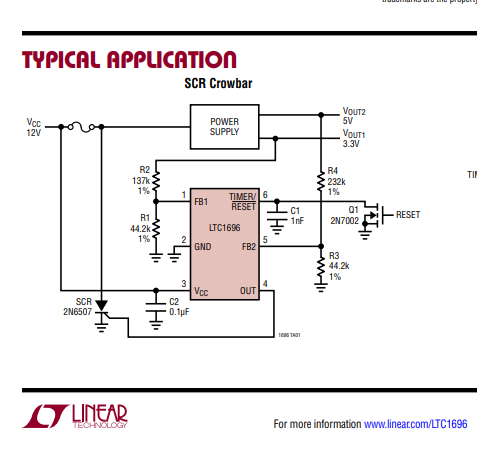
I've noticed the stand alone overvoltage switches are not as readily available and I asked a friend of mine if he would put together a board using an IC provided by Analog Devices.


https://www.analog.com/media/en/technical-documentation/data-sheets/1696fb.pdf


So, my friend completed the design and is sending to me, what he says, are well operating switches.  I'll test the switches when they arrive in a few days but  I'd like to ask for any feedback on the design. (see attached pdf of the schematic).


He says the device behaves as expected, tripping is adjustable from 15 to 18 volts and running current is less than 5 ma.  The R5 is not used and is included only to allow for a fixed trip point (rather than adjustable with the pot).


Thanks in advance for any comments.

Dan Theis
| | - The Matronics AeroElectric-List Email Forum - | | | Use the List Feature Navigator to browse the many List utilities available such as the Email Subscriptions page, Archive Search & Download, 7-Day Browse, Chat, FAQ, Photoshare, and much more:
http://www.matronics.com/Navigator?AeroElectric-List |
|
| Description: |
|
| Filesize: |
37.62 KB |
| Viewed: |
3381 Time(s) |
|
| Description: |
|
| Filesize: |
69.04 KB |
| Viewed: |
3381 Time(s) |
|
| Description: |
|

Download |
| Filename: |
OverVolt_0 (1).pdf |
| Filesize: |
21.96 KB |
| Downloaded: |
139 Time(s) |
| Description: |
|
Download |
| Filename: |
OverVolt_0 (1).pdf |
| Filesize: |
21.96 KB |
| Downloaded: |
127 Time(s) |
_________________
Dan Theis
Scratch building Sonex #1362
Still working on the Revmaster Alternator improvement |
|
| Back to top |
|
 |
Ceengland
Joined: 11 Oct 2020
Posts: 381
Location: MS
|
| Posted: Thu Nov 18, 2021 6:13 am Post subject: Over Voltage Crowbar |
|
|
On Wed, Nov 17, 2021 at 9:20 PM dj_theis <djtheis58(at)gmail.com (djtheis58(at)gmail.com)> wrote:
| Quote: | --> AeroElectric-List message posted by: "dj_theis" <djtheis58(at)gmail.com (djtheis58(at)gmail.com)>
I've noticed the stand alone overvoltage switches are not as readily available and I asked a friend of mine if he would put together a board using an IC provided by Analog Devices.
https://www.analog.com/media/en/technical-documentation/data-sheets/1696fb.pdf
So, my friend completed the design and is sending to me, what he says, are well operating switches. I'll test the switches when they arrive in a few days but I'd like to ask for any feedback on the design. (see attached pdf of the schematic).
He says the device behaves as expected, tripping is adjustable from 15 to 18 volts and running current is less than 5 ma. The R5 is not used and is included only to allow for a fixed trip point (rather than adjustable with the pot).
Thanks in advance for any comments.
Dan Theis
|
Looks nice. Are you planning on selling the completed modules? If not, what's a guestimate of component prices?
Charlie
| | - The Matronics AeroElectric-List Email Forum - | | | Use the List Feature Navigator to browse the many List utilities available such as the Email Subscriptions page, Archive Search & Download, 7-Day Browse, Chat, FAQ, Photoshare, and much more:
http://www.matronics.com/Navigator?AeroElectric-List |
|
_________________
Charlie |
|
| Back to top |
|
|
dj_theis
Joined: 28 Aug 2017
Posts: 56
Location: Minnesota
|
| Posted: Thu Nov 18, 2021 7:19 am Post subject: Re: Over Voltage Crowbar |
|
|
| Quote: | | Looks nice. Are you planning on selling the completed modules? If not, what's a guestimate of component prices? |
Thanks Charlie, that means a lot coming from you.
I'd be happy to pass on completed modules to anyone interested. My buddy put in the time to design the board and construct the test modules so I'm not sure its ethical to pass his full design off. I did ask him if he minded if I solicited for feedback from this group and he had no issues with that. The original circuit design is (obviously) from the IC manufacturer and it is (I believe) easy enough to duplicate.
I think the retail price would fall in the range of $28 which would pay for shipping and the time required to manage orders. I have no experience doing this kind of thing and really don't see it as a path to retirement ;0)
Having said that, I don't do any of this OBAM stuff for monetary gain. I'm involved because I was born to learn and love to "make stuff work." So, if there is interest in any order larger than quantity 3, I'd be willing to execute the production process and pass on the modules at pennies over my cost for the completed modules.
Speaking of cost; The components alone in small quantities is very close to $10. I'm not sure that is with the PC board but the real estate is small so if the quantities are large the board cost is minimal.
I'll test the module more thoroughly when I receive them and report on the forum.
Dan Theis
(Still working on the Revmaster alternator issue...)
| | - The Matronics AeroElectric-List Email Forum - | | | Use the List Feature Navigator to browse the many List utilities available such as the Email Subscriptions page, Archive Search & Download, 7-Day Browse, Chat, FAQ, Photoshare, and much more:
http://www.matronics.com/Navigator?AeroElectric-List |
|
_________________
Dan Theis
Scratch building Sonex #1362
Still working on the Revmaster Alternator improvement |
|
| Back to top |
|
|
ashleysc(at)broadstripe.n
Guest
|
| Posted: Thu Nov 18, 2021 8:52 am Post subject: Over Voltage Crowbar |
|
|
Hi Dan;
What's the maximum alternator size (amp output) that this device can handle?
Cheers! Stu.
From: "Charlie England" <ceengland7(at)gmail.com>
To: "aeroelectric list" <aeroelectric-list(at)matronics.com>
Sent: Thursday, November 18, 2021 6:11:56 AM
Subject: Re: Over Voltage Crowbar
On Wed, Nov 17, 2021 at 9:20 PM dj_theis <djtheis58(at)gmail.com (djtheis58(at)gmail.com)> wrote:
| Quote: | --> AeroElectric-List message posted by: "dj_theis" <djtheis58(at)gmail.com (djtheis58(at)gmail.com)>
I've noticed the stand alone overvoltage switches are not as readily available and I asked a friend of mine if he would put together a board using an IC provided by Analog Devices.
https://www.analog.com/media/en/technical-documentation/data-sheets/1696fb.pdf
So, my friend completed the design and is sending to me, what he says, are well operating switches. I'll test the switches when they arrive in a few days but I'd like to ask for any feedback on the design. (see attached pdf of the schematic).
He says the device behaves as expected, tripping is adjustable from 15 to 18 volts and running current is less than 5 ma. The R5 is not used and is included only to allow for a fixed trip point (rather than adjustable with the pot).
Thanks in advance for any comments.
Dan Theis
|
Looks nice. Are you planning on selling the completed modules? If not, what's a guestimate of component prices?
Charlie
| | - The Matronics AeroElectric-List Email Forum - | | | Use the List Feature Navigator to browse the many List utilities available such as the Email Subscriptions page, Archive Search & Download, 7-Day Browse, Chat, FAQ, Photoshare, and much more:
http://www.matronics.com/Navigator?AeroElectric-List |
|
|
|
| Back to top |
|
|
Eric Page
Joined: 15 Feb 2017
Posts: 243
|
| Posted: Thu Nov 18, 2021 10:36 am Post subject: Re: Over Voltage Crowbar |
|
|
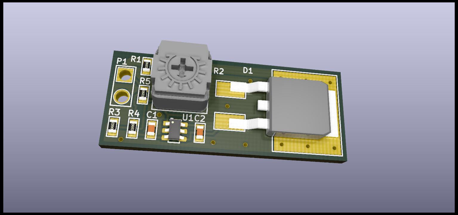
Looking at the 3D rendering image that you posted, I would be worried about the board layout.  If the trace under the "R2" and "D1" markings is the only copper carrying trip current to the SCR, and if it's as narrow as it appears, then I'm concerned that the trace may burn open before it can blow the fuse.  Blowing a typical fuse in a reasonably short time takes significantly more than its rated current.


See the time-vs-current chart in this datasheet, as an example: https://tinyurl.com/29c28u3y+


If your friend also used bottom side copper to carry trip current then it may be fine; I just can't tell from the image you posted since it only shows the top side copper.  I would definitely perform a full function test by connecting it to a car battery through a fuse with the same current rating that you intend to use, then wind down the pot until it trips (wear a glove and eye protection; a blown trace can throw molten copper).  If the fuse blows with no damage to the board, then you've got a winner.


If not, then a better layout would put the SCR right next to the input wires with large copper pours connecting its anode to the input and its cathode to ground.  The controller IC, potentiometer and passives can go at the other end of the board.


Do you happen to know why there are four resistors on the board?  Establishing a trip range only requires two resistors and the pot.
| | - The Matronics AeroElectric-List Email Forum - | | | Use the List Feature Navigator to browse the many List utilities available such as the Email Subscriptions page, Archive Search & Download, 7-Day Browse, Chat, FAQ, Photoshare, and much more:
http://www.matronics.com/Navigator?AeroElectric-List |
|
|
|
| Back to top |
|
|
dj_theis
Joined: 28 Aug 2017
Posts: 56
Location: Minnesota
|
| Posted: Thu Nov 18, 2021 10:41 am Post subject: Re: Over Voltage Crowbar |
|
|
| Quote: | What's the maximum alternator size (amp output) that this device can handle?
Cheers! Stu. |
HI Stu,
The device does not conduct any charge current from the alternator. So, there is no relationship to alternator output or any limitation relative to alternator sizing.
If you look at Professor Nuckolls' overvoltage design, (which this device emulates) the control relay's circuit protection is simply tripped if the bus voltage sensed exceeds the setpoint of the switch.
So the current through the switch is insignificant when in standby (monitor) mode (< 5 ma) and will briefly short circuit the power source feeding a relay if the bus voltage rises above the limilt of the overvoltage circuit. That short circuit current is limited by the (typically 2 amp) circuit breaker feeding the relay.
The device is wired identical to any of the O.V, switches shown in any of the Aeroelectric standard circuits.
| | - The Matronics AeroElectric-List Email Forum - | | | Use the List Feature Navigator to browse the many List utilities available such as the Email Subscriptions page, Archive Search & Download, 7-Day Browse, Chat, FAQ, Photoshare, and much more:
http://www.matronics.com/Navigator?AeroElectric-List |
|
_________________
Dan Theis
Scratch building Sonex #1362
Still working on the Revmaster Alternator improvement |
|
| Back to top |
|
|
user9253
Joined: 28 Mar 2008
Posts: 1908
Location: Riley TWP Michigan
|
| Posted: Thu Nov 18, 2021 4:29 pm Post subject: Re: Over Voltage Crowbar |
|
|
If nuisance tripping occurs, a capacitor (s) connected between U1 Pin 1 (FB1) and ground might help.

-

Eric, post 1 explains that R5 is optional to eliminate the pot.
| | - The Matronics AeroElectric-List Email Forum - | | | Use the List Feature Navigator to browse the many List utilities available such as the Email Subscriptions page, Archive Search & Download, 7-Day Browse, Chat, FAQ, Photoshare, and much more:
http://www.matronics.com/Navigator?AeroElectric-List |
|
_________________
Joe Gores |
|
| Back to top |
|
|
Eric Page
Joined: 15 Feb 2017
Posts: 243
|
| Posted: Fri Nov 19, 2021 8:42 am Post subject: Re: Over Voltage Crowbar |
|
|
| user9253 wrote: | | Eric, post 1 explains that R5 is optional to eliminate the pot. |
Yep, I saw that, but it doesn't explain four resistors on the board. Perhaps single E96 resistors didn't offer the exact values needed, but end-of-range precision isn't important and you'd end up with a tolerance stack anyway.
I guess it doesn't really matter; I was just curious about it.
| | - The Matronics AeroElectric-List Email Forum - | | | Use the List Feature Navigator to browse the many List utilities available such as the Email Subscriptions page, Archive Search & Download, 7-Day Browse, Chat, FAQ, Photoshare, and much more:
http://www.matronics.com/Navigator?AeroElectric-List |
|
|
|
| Back to top |
|
|
dj_theis
Joined: 28 Aug 2017
Posts: 56
Location: Minnesota
|
| Posted: Fri Nov 19, 2021 10:43 am Post subject: Re: Over Voltage Crowbar |
|
|
| Quote: | | Looking at the 3D rendering image that you posted, I would be worried about the board layout. If the trace under the "R2" and "D1" markings is the only copper carrying trip current to the SCR, and if it's as narrow as it appears, then I'm concerned that the trace may burn open before it can blow the fuse. Blowing a typical fuse in a reasonably short time takes significantly more than its rated current |
Thanks for the observation Eric. A good question and I'll ask about it.
Yes, I had planned to test the board extensively (with a battery driven circuit) when they arrive.
With regard to the resistors, no doubt that addiing the components seems rather arbitrary to me as well, particularly R5. The pot + R1 was a convienience related to resistor sizing and availablility.
| | - The Matronics AeroElectric-List Email Forum - | | | Use the List Feature Navigator to browse the many List utilities available such as the Email Subscriptions page, Archive Search & Download, 7-Day Browse, Chat, FAQ, Photoshare, and much more:
http://www.matronics.com/Navigator?AeroElectric-List |
|
_________________
Dan Theis
Scratch building Sonex #1362
Still working on the Revmaster Alternator improvement |
|
| Back to top |
|
|
dj_theis
Joined: 28 Aug 2017
Posts: 56
Location: Minnesota
|
| Posted: Fri Nov 19, 2021 10:50 am Post subject: Re: Over Voltage Crowbar |
|
|
| Quote: | | If nuisance tripping occurs, a capacitor (s) connected between U1 Pin 1 (FB1) and ground might help |
Thanks Joe,
I meant to include the data sheet for U1 in my original post and on page 10 (I believe) they define modifying C1 to achieve a debounce desired.
https://www.analog.com/media/en/technical-documentation/data-sheets/1696fb.pdf
I think the existing selection provides a time delay of 10 to 11 usec, depending on the voltage sensed. Yes, I think you are correct that this might be a bit too "twitchy." Using the added cap as you suggest is certainly an easy way to modify the behavior without component replacement. Something that might be necessary for any specific aplication.
| | - The Matronics AeroElectric-List Email Forum - | | | Use the List Feature Navigator to browse the many List utilities available such as the Email Subscriptions page, Archive Search & Download, 7-Day Browse, Chat, FAQ, Photoshare, and much more:
http://www.matronics.com/Navigator?AeroElectric-List |
|
_________________
Dan Theis
Scratch building Sonex #1362
Still working on the Revmaster Alternator improvement |
|
| Back to top |
|
|
nuckolls.bob(at)aeroelect
Guest
|
| Posted: Wed Nov 24, 2021 10:01 am Post subject: Over Voltage Crowbar |
|
|
| Quote: |
I think the existing selection provides a time delay of 10 to 11 usec, depending on the voltage sensed. Yes, I think you are correct that this might be a bit too "twitchy." Using the added cap as you suggest is certainly an easy way to modify the behavior without component replacement. Something that might be necessary for any specific aplication. |
Legacy qualification for 14v avionics cites
a requirement to stand off a 20v surge for
1 Second; 40v surge for 100 mS.
Waaayyyy back when, we adjusted ov trip time
constants to respond to a 14.2 to 20V step
input in 50 plus or minus a few milliseconds.
While 'useful' it was far faster than necessary
and occasionally caused problems with nuisance
tripping.
If I were updating the OVM14, it would be
processor based with a software timer that
trips for any voltage event exceeding
15 volts by more than 500 mS. If the input
drops below 16v before time-out, the timer
resets and starts over.
In any case, your trip response time target is
defined in HUNDREDS of milliseconds.
Bob . . .
Un impeachable logic: George Carlin asked, "If black boxes
survive crashes, why don't they make the whole airplane
out of that stuff?"
| | - The Matronics AeroElectric-List Email Forum - | | | Use the List Feature Navigator to browse the many List utilities available such as the Email Subscriptions page, Archive Search & Download, 7-Day Browse, Chat, FAQ, Photoshare, and much more:
http://www.matronics.com/Navigator?AeroElectric-List |
|
|
|
| Back to top |
|
|
|
|
You cannot post new topics in this forum
You cannot reply to topics in this forum
You cannot edit your posts in this forum
You cannot delete your posts in this forum
You cannot vote in polls in this forum
You cannot attach files in this forum
You can download files in this forum
|
Powered by phpBB © 2001, 2005 phpBB Group
|

