 |
Matronics Email Lists
Web Forum Interface to the Matronics Email Lists
|
| View previous topic :: View next topic |
| Author |
Message |
cluros(at)gmail.com
Guest
|
 Posted: Wed Nov 10, 2021 2:37 pm Post subject: EFII System32 Posted: Wed Nov 10, 2021 2:37 pm Post subject: EFII System32 |
 |
|
In a belated attempt to not derail Michael's electrical system thread, I'm starting this one to ask Charlie for more details on the possible problems with EFII's System32 fuel injection and ignition system when the electrical system architecture is based on the EFII Bus Manager.


I have been hired to test fly an aircraft with this system. Haven't been able to get off the ground yet due to multiple setup problems and wiring mistakes but none of these were related to the Bus Manager.

Charlie I would be very interested to hear anything you have to say FMEA wise about this system.
| | - The Matronics AeroElectric-List Email Forum - | | | Use the List Feature Navigator to browse the many List utilities available such as the Email Subscriptions page, Archive Search & Download, 7-Day Browse, Chat, FAQ, Photoshare, and much more:
http://www.matronics.com/Navigator?AeroElectric-List |
|
|
|
| Back to top |
|
 |
Ceengland
Joined: 11 Oct 2020
Posts: 379
Location: MS
|
| Posted: Wed Nov 10, 2021 5:40 pm Post subject: EFII System32 |
|
|
On 11/10/2021 4:35 PM, Sebastien wrote:
| Quote: | In a belated attempt to not derail Michael's electrical system thread,
I'm starting this one to ask Charlie for more details on the possible
problems with EFII's System32 fuel injection and ignition system when
the electrical system architecture is based on the EFII Bus Manager.
I have been hired to test fly an aircraft with this system. Haven't
been able to get off the ground yet due to multiple setup problems and
wiring mistakes but none of these were related to the Bus Manager.
Charlie I would be very interested to hear anything you have to say
FMEA wise about this system.
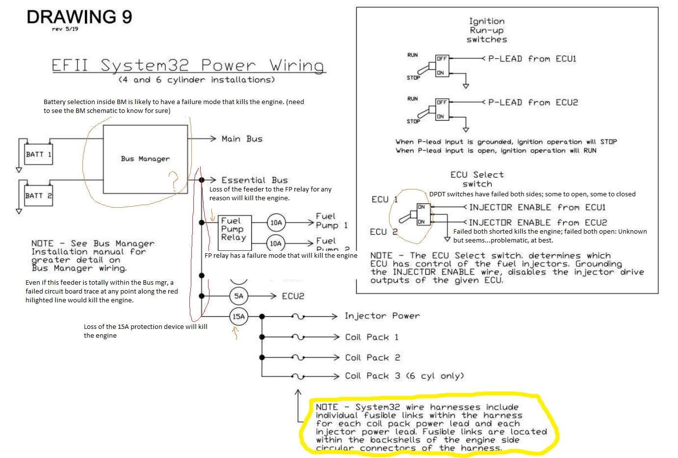
OK, for a start, here's a marked up copy of that page from the install
|
manual. I've likely overlooked some stuff in the quick run-through I
did, and could be more accurate with an internal schematic + board
layout of the Bus Manager. But I've marked six ways the system can kill
the engine, and highlighted a seventh *possible* way; I'd want to see
exactly how up to twelve fusible links are installed within the
backshell of the BM connector. Fusible links may or may not generate
enough heat to be a factor in any wire near them. They're typically
thermally insulated to protect other wires around them but they're
typically not tightly confined in an enclosure (the backshell, in this
case).
As I said, it's difficult to completely evaluate the system without the
BM info. The drawing shows an external 'daisy chain' connection path
(circled in red) to the various components, but the yellow circled text
seems to indicate that path is inside the BM. Having said that, things
like the ECU select switch are likely to be external.
Hope that's at least some food for thought, and maybe others will have
some input, as well.
Charlie
--
This email has been checked for viruses by Avast antivirus software.
https://www.avast.com/antivirus
| | - The Matronics AeroElectric-List Email Forum - | | | Use the List Feature Navigator to browse the many List utilities available such as the Email Subscriptions page, Archive Search & Download, 7-Day Browse, Chat, FAQ, Photoshare, and much more:
http://www.matronics.com/Navigator?AeroElectric-List |
|
| Description: |
|
| Filesize: |
266.34 KB |
| Viewed: |
1357 Time(s) |
|
_________________
Charlie |
|
| Back to top |
|
|
cluros(at)gmail.com
Guest
|
| Posted: Thu Nov 11, 2021 7:28 pm Post subject: EFII System32 |
|
|
Thank you Charlie,
1. What is the failure mode of the relay that could kill the engine?
2. You mentioned DPDT switches can fail to both shorted, is this something that happens when you flip the switch or can the switch just be sitting there and fail?
Thank you,
Sebastien
On Wed, Nov 10, 2021 at 5:44 PM Charlie England <ceengland7(at)gmail.com (ceengland7(at)gmail.com)> wrote:
| Quote: | On 11/10/2021 4:35 PM, Sebastien wrote:
> In a belated attempt to not derail Michael's electrical system thread,
> I'm starting this one to ask Charlie for more details on the possible
> problems with EFII's System32 fuel injection and ignition system when
> the electrical system architecture is based on the EFII Bus Manager.
>
> I have been hired to test fly an aircraft with this system. Haven't
> been able to get off the ground yet due to multiple setup problems and
> wiring mistakes but none of these were related to the Bus Manager.
>
> Charlie I would be very interested to hear anything you have to say
> FMEA wise about this system.
OK, for a start, here's a marked up copy of that page from the install
manual. I've likely overlooked some stuff in the quick run-through I
did, and could be more accurate with an internal schematic + board
layout of the Bus Manager. But I've marked six ways the system can kill
the engine, and highlighted a seventh *possible* way; I'd want to see
exactly how up to twelve fusible links are installed within the
backshell of the BM connector. Fusible links may or may not generate
enough heat to be a factor in any wire near them. They're typically
thermally insulated to protect other wires around them but they're
typically not tightly confined in an enclosure (the backshell, in this
case).
As I said, it's difficult to completely evaluate the system without the
BM info. The drawing shows an external 'daisy chain' connection path
(circled in red) to the various components, but the yellow circled text
seems to indicate that path is inside the BM. Having said that, things
like the ECU select switch are likely to be external.
Hope that's at least some food for thought, and maybe others will have
some input, as well.
Charlie
--
This email has been checked for viruses by Avast antivirus software.
https://www.avast.com/antivirus
|
| | - The Matronics AeroElectric-List Email Forum - | | | Use the List Feature Navigator to browse the many List utilities available such as the Email Subscriptions page, Archive Search & Download, 7-Day Browse, Chat, FAQ, Photoshare, and much more:
http://www.matronics.com/Navigator?AeroElectric-List |
|
|
|
| Back to top |
|
|
nuckolls.bob(at)aeroelect
Guest
|
| Posted: Wed Nov 17, 2021 9:24 am Post subject: EFII System32 |
|
|
| Quote: |
OK, for a start, here's a marked up copy of that page from the install
manual. I've likely overlooked some stuff in the quick run-through I
did, and could be more accurate with an internal schematic + board
layout of the Bus Manager. But I've marked six ways the system can kill
the engine, and highlighted a seventh *possible* way; I'd want to see
exactly how up to twelve fusible links are installed within the
backshell of the BM connector. Fusible links may or may not generate
enough heat to be a factor in any wire near them. They're typically
thermally insulated to protect other wires around them but they're
typically not tightly confined in an enclosure (the backshell, in this
case). |
Fusible links are NOT replacements for fuses.
Fusible links are ROBUST protection against
hard faults and are used in power distribution
feeders like alternator b-leads, extension feeders
between busses, some battery installations, etc.
They are RARELY suited for protection of
individual loads.
What is the rational for protecting these
feeders individually in the first place?
Manufacturer's recommendations? Consider
REAL fuses if a FMEA warrants such protection.
Bob . . .
Un impeachable logic: George Carlin asked, "If black boxes
survive crashes, why don't they make the whole airplane
out of that stuff?"
| | - The Matronics AeroElectric-List Email Forum - | | | Use the List Feature Navigator to browse the many List utilities available such as the Email Subscriptions page, Archive Search & Download, 7-Day Browse, Chat, FAQ, Photoshare, and much more:
http://www.matronics.com/Navigator?AeroElectric-List |
|
|
|
| Back to top |
|
|
Ceengland
Joined: 11 Oct 2020
Posts: 379
Location: MS
|
| Posted: Wed Nov 17, 2021 2:36 pm Post subject: EFII System32 |
|
|
On Wed, Nov 17, 2021 at 11:28 AM Robert L. Nuckolls, III <nuckolls.bob(at)aeroelectric.com (nuckolls.bob(at)aeroelectric.com)> wrote:
| Quote: | | Quote: |
OK, for a start, here's a marked up copy of that page from the install
manual. I've likely overlooked some stuff in the quick run-through I
did, and could be more accurate with an internal schematic + board
layout of the Bus Manager. But I've marked six ways the system can kill
the engine, and highlighted a seventh *possible* way; I'd want to see
exactly how up to twelve fusible links are installed within the
backshell of the BM connector. Fusible links may or may not generate
enough heat to be a factor in any wire near them. They're typically
thermally insulated to protect other wires around them but they're
typically not tightly confined in an enclosure (the backshell, in this
case). |
Fusible links are NOT replacements for fuses.
Fusible links are ROBUST protection against
hard faults and are used in power distribution
feeders like alternator b-leads, extension feeders
between busses, some battery installations, etc.
They are RARELY suited for protection of
individual loads.
What is the rational for protecting these
feeders individually in the first place?
Manufacturer's recommendations? Consider
REAL fuses if a FMEA warrants such protection.
Bob . . .
|
I'll take another swing, since I wrote the quoted text (it should be obvious from the text that I don't care for the actual product being discussed).
My yet-to-fly EFI (NOT FlyEFII) has separate fuses for each injector and each coil. The reason I did it is that it's dirt simple to do, weighs only a few ounces, and isolates each item from all the rest in case of a failure. No doubt that's why FlyEFII used individual fusible links, too.
Logic: If running a carb, you can't isolate fuel delivery to each cylinder; you're stuck with one delivery point. Not much difference with 'traditional' a/c fuel injection. But with electronic injection and dual controllers, it's relatively easy to isolate the feed to each device so that a failure along one path will not cause the entire system to go down. That kind of issue is what I was trying to describe in the marked-up version of the wiring diagram; eliminating points where a single failure takes the entire system (in this case, the engine) offline. I consider being able to effectively isolate each cylinder (or pair of cylinders, with some coils) to be a significant advantage with electronic injection over traditional systems. (I do recognize that the added installation complexity can be a negative factor.)
As to the fusible link vs fuse question: I used links in several (all?) the places you mention, for the same reasons; they're as reliable as the wire itself, fewer mechanical joints, and the only reason they would ever need to act is in a catastrophic fault situation. While I haven't installed them for my injectors & coils, I can see justification for using them there, for the same reasons. One shorted coil or one shorted injector will almost certainly burn itself open before either its fuse or, if used, a fusible link would activate. So the only reason for branch protection is the catastrophic failure mode of a shorted wire. Using the links reduces the number of mechanical joints (transitions) in the path to the device.
FWIW,
Charlie
| | - The Matronics AeroElectric-List Email Forum - | | | Use the List Feature Navigator to browse the many List utilities available such as the Email Subscriptions page, Archive Search & Download, 7-Day Browse, Chat, FAQ, Photoshare, and much more:
http://www.matronics.com/Navigator?AeroElectric-List |
|
_________________
Charlie |
|
| Back to top |
|
|
nuckolls.bob(at)aeroelect
Guest
|
| Posted: Wed Nov 17, 2021 3:02 pm Post subject: EFII System32 |
|
|
| Quote: |
I'll take another swing, since I wrote the quoted text (it should be obvious from the text that I don't care for the actual product being discussed).
My yet-to-fly EFI (NOT FlyEFII) has separate fuses for each injector and each coil. The reason I did it is that it's dirt simple to do, weighs only a few ounces, and isolates each item from all the rest in case of a failure. No doubt that's why FlyEFII used individual fusible links, too. |
Okay, if that's what the mfgr wants. But generally
speaking, fusible links are in the same class of
protection as the ANL current limiters. They take
10x longer to open under same 'rated' loads . . .
and make smoke.
Also watch for situations where one fusible
link is supplied from another fusible link
upstream. You have a I(squared)R timing
dynamic to consider for series connected
circuit protection.
Bob . . .
Un impeachable logic: George Carlin asked, "If black boxes
survive crashes, why don't they make the whole airplane
out of that stuff?"
| | - The Matronics AeroElectric-List Email Forum - | | | Use the List Feature Navigator to browse the many List utilities available such as the Email Subscriptions page, Archive Search & Download, 7-Day Browse, Chat, FAQ, Photoshare, and much more:
http://www.matronics.com/Navigator?AeroElectric-List |
|
|
|
| Back to top |
|
|
|
|
You cannot post new topics in this forum
You cannot reply to topics in this forum
You cannot edit your posts in this forum
You cannot delete your posts in this forum
You cannot vote in polls in this forum
You cannot attach files in this forum
You can download files in this forum
|
Powered by phpBB © 2001, 2005 phpBB Group
|

