 |
Matronics Email Lists
Web Forum Interface to the Matronics Email Lists
|
| View previous topic :: View next topic |
| Author |
Message |
ashleysc(at)broadstripe.n
Guest
|
 Posted: Thu Nov 11, 2021 10:09 am Post subject: RV-10 Electrical Review with Electric AC and FlyEFII Posted: Thu Nov 11, 2021 10:09 am Post subject: RV-10 Electrical Review with Electric AC and FlyEFII |
 |
|
Hi Charlie;
Hi All;
I apologize beforehand if this comment is out of context. I didn't read all the foregoing. But I'll make it brief:
1. The aircraft has two fuel tanks, one in each wing.
2. It has a "Main " pump which can draw from either tank and two "Auxiliary" pumps (a right aux and a left aux).
3. Any one of these three pumps were proved to be able to provide 1.9 to 2.0 times the requisite fuel for wide open throttle, with the aircraft tilted at 20 degrees up attitude and one gallon of fuel remaining in the tanks.
4. Since the carburetor has a pressure regulator and vapor return line, the pumps cannot over-pressure the system.
5. Each pump has its own switch/circuit breaker.
6.The pump failure mode is to "fail open," that is fuel will flow through a failed pump.
7. There are two 20 amp alternators in the aircraft, which can operate singly or in parallel.
8. So, to summarize: It would take the failure of three pumps, or three switches, or two alternators to incapacitate the aircraft.
Cheers! Stu.
From: "Charlie England" <ceengland7(at)gmail.com>
To: aeroelectric-list(at)matronics.com
Sent: Wednesday, November 10, 2021 2:15:52 PM
Subject: Re: Re: RV-10 Electrical Review with Electric AC and FlyEFII
It *might* work, if you could dial the pressure up to electronic injection levels. The pump is possibly capable of that much pressure; but I just don't know if Andair would configure it that way. There's also the issue of additive pressure, though I suppose that if you kept the bypass regulator between the 2nd pump & the engine, it would probably work. I'd want test data; either my own or the pump mfgr's before installing that kind of setup.
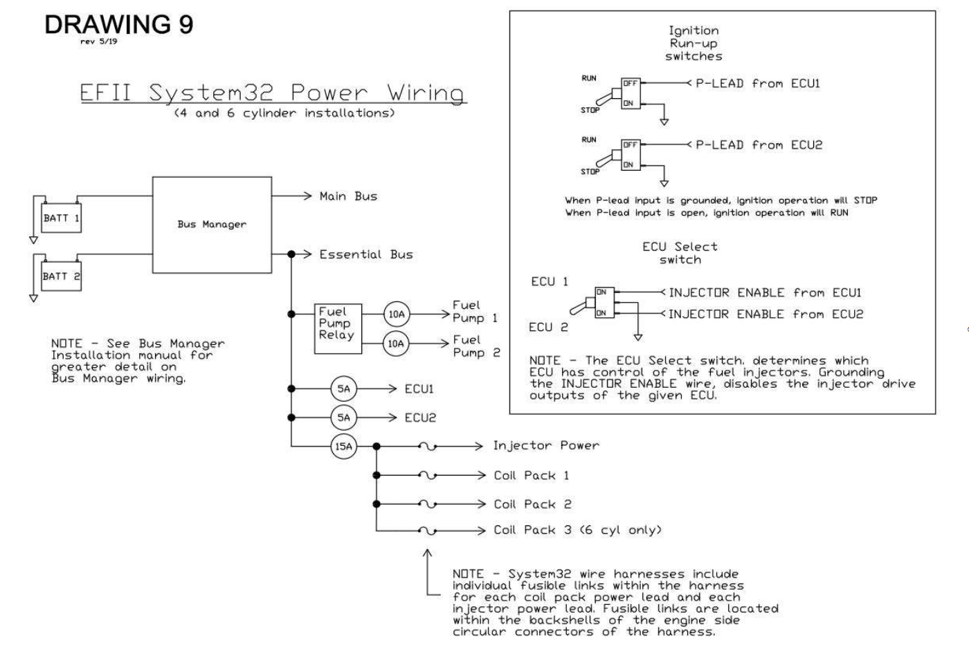
I just downloaded the System32 install manual and scrolled down to the power wiring page. I tried to find the Bus Manager install manual (ref by the NOTE on this page), but couldn't find it on their web site. Comments are based on what I can see, with available docs from the mfgr that I could find.
Looking at the diagram, I see three (3) (scratch that; at least 6; likely quite a few more if I could see inside the box) single points of failure, on this one page, any one of which *would* stop the engine. Depending on how you count failures, I can see closer to a dozen. All of those failure modes are hardware related; they don't count control logic (inside the 'black boxes'), which I can't see. Now some of them are quite unlikely, but some have a much higher probability of occurring, and there are relatively simple fixes for all of them. (Doing FMEA doesn't really look at probabilities; it looks at Effects.) I keep coming back to the mantra of: if it's nearly impossible to make redundant (like the wing spar, or only one throttle body on the engine), I'll evaluate and likely accept the risk, but if it's relatively easy to provide a backup for flight critical items, I'm going to find a way to do it.
Please believe me when I say I'm truly not trying to be insulting, but I would not want to fly in a plane wired like that. There's just not a diplomatic way to tell someone that an easily corrected thing could kill them if not corrected. If I haven't offended you System32 users too much and you're interested, we can discuss some of the failure modes and ideas to fix them.
Charlie
[img]cid:part1.QJMFauNX.6IsT0ksr(at)gmail.com[/img]
On 11/10/2021 2:59 PM, Sebastien wrote:
| Quote: | No argument about other black boxes Charlie, I was just trying to point out that the EFII fuel pump black box is a control circuit, not a power circuit. The output to the fuel pump relay is one wire. If the black box end of that wire goes to ground, or open, or 15v, or whatever, the fuel pump keeps running.
As for inline fuel pumps, I hadn't run into that problem yet. Would this not work?
Andair Products
On Wed, Nov 10, 2021 at 10:51 AM Charlie England <ceengland7(at)gmail.com (ceengland7(at)gmail.com)> wrote:
| Quote: | Your example of the GNS + VOR/ILS is the perfect example of proper 'what if' thinking; if the GNS availability is down for any reason, you have an independent method of accomplishing your goal. 'Black box' control of the fuel pumps (or any other multiple device backup system) might or might not meet those criteria. It's been demonstrated that some of them do not accomplish this, and some have been demonstrated to have failure modes that can take out *everything* they supply power to. I'm just trying to point out that saying that it's worked for X hours or Y years just says that you haven't seen a failure mode yet that could affect both the primary and the backup. Without analyzing the circuits in the box, you don't know the failure modes. Completely different situation from two separate radio systems with separate power sources, antennas, etc.
My point about the fuel pumps is knowing the product when it isn't 'traditional'. The fuel pumps used by FLYEFII (and others) for electronic injection are *not* like traditional fuel pumps. Unlike traditional Lyc engine driven pumps, and unlike the traditional boost pumps, those Walbro pumps will *not* pass fuel if they aren't running.
I don't know of any 'different pump' that you could run that would supply the needed ~40 PSI and could still be run in series without any issues. If you know of one, please share the info; it could well simplify a lot of EFI installations.
Charlie
On 11/10/2021 11:58 AM, Sebastien wrote:
| Quote: | | Quote: | | Or just use different pumps and run them in series (the way a legacy system is installed) instead of in parallel with FLYEFII's manifold. |
| Quote: |
As a FYI, the Walbro pumps shown on FLYEFII's web page are positive displacement pumps. That means that if the pump isn't turning, no fuel will move through that pump. See the problem with that thought path? |
I can't say that I do Charlie:
| Quote: | | Or just use different pumps and run them in series (the way a legacy system is installed) instead of in parallel with FLYEFII's manifold. |
When selecting fuel pumps, the ability to flow fuel when not turning has been a basic requirement for series fuel pumps for about a century. The fuel flow test performed before first flight will demonstrate whether or not the correct pumps have been selected.
As for the black box, it is completely unnecessary to analyze the failure modes and their effects since any failure of the box (including a bad tempered Gremlin eating the box and leaving the wires dangling) will either leave the relay powering the primary fuel pump as normal, or erroneously switch to backup. The particular aircraft I've been working on has been flying around with a failed black box since day one. The black box is in a different country than the aircraft. The pump still runs.
Similarly the Mooney I fly has a complicated Garmin GNS Navigator and a backup VOR/ILS. I have no need to analyse the different failure modes of the Garmin in order to be confident that if it fails, I can use the other VOR/ILS. I just tune, identify, switch HSI source, set course, and set the desired autopilot mode.
However relay failures are something I know nothing about. If a likely failure mode of this relay could leave both pumps unpowered then the FLYEFII implementation is poor. I haven't seen any data to suggest this but I'll ask them what research and testing they did next time I speak with them.
On Wed, Nov 10, 2021 at 9:06 AM Charlie England <ceengland7(at)gmail.com (ceengland7(at)gmail.com)> wrote:
| Quote: | Everyone sets their own comfort level when it comes to risk. If you're happy *and you're fully informed about the risks*, then that's your choice. I might make different choices, and some of mine on other subjects might be unacceptable to you.
Do you *know* what's in the black box? Have you analyzed the failure modes and their effects? A fuel line failure would be difficult to 'plan around', except through careful and thoughtful installation work. But electrical failure issues are relatively simple to plan for and to implement backup systems for potential failures. I'm just trying to point out that there are some whizbang gadgets that can introduce more failure modes than they compensate for, and we need to know when that is happening.
I'd have more confidence in a vendor's position if he told me that he tested for a potential problem, rather than just speculation. For instance, I asked one of the a/c fuel boost pump (for conventional fuel injection) vendors about their technique of looping bypassed fuel back to the inlet of the pump and the risks of vapor lock/cavitation. His response was that they'd tested it, including at elevated fuel temps. There's also the contrary data point that competitors' systems (using very similar dual pump setups) work just fine when running both pumps for takeoff & landing.
I really want to understand as well as possible any system I install that's a departure from 'tradition', simply because failure modes will be different and likely not as well documented. For instance, this:
Or just use different pumps and run them in series (the way a legacy system is installed) instead of in parallel with FLYEFII's manifold.
As a FYI, the Walbro pumps shown on FLYEFII's web page are positive displacement pumps. That means that if the pump isn't turning, no fuel will move through that pump. See the problem with that thought path?
Charlie
On 11/10/2021 10:17 AM, Sebastien wrote:
| Quote: | Charlie if the "black box" that switches fuel pumps fails, the primary fuel pump continues to run so no worries. The relay that switches pumps is NO passing current to the primary pump, or energized and switching current to the backup pump. I suppose the relay itself could be mechanically damaged and shut off both pumps, but a fuel line could break cutting off fuel as well.
The FLYEFII Bus Manager is expensive and requires two batteries, but it's actually a pretty well thought out unit.
It just occurred to me that in our high wing we're not worried about cavitating the pumps if we run both, but in an RV-10 it could be a concern. So instead of fancy switching logic, install a third pump to feed the two EFII pumps and run all three for takeoff  . Or just use different pumps and run them in series (the way a legacy system is installed) instead of in parallel with FLYEFII's manifold. . Or just use different pumps and run them in series (the way a legacy system is installed) instead of in parallel with FLYEFII's manifold.
On Wed, Nov 10, 2021 at 7:11 AM Charlie England <ceengland7(at)gmail.com (ceengland7(at)gmail.com)> wrote:
| Quote: | The fuel pump symptoms you describe are totally normal. If you run both pumps, they will each require their own full rated current while running. Total fuel pressure shouldn't change more than a few PSI if the regulator is sized properly. Excess fuel is bypassed by the regulator back to the tank. Upside is that if one pump fails during a critical phase of flight, fuel delivery doesn't even 'hiccup'.
Auto-switching of the pumps: If that's totally inside your 'black box', do you *know* that black box doesn't have a single-point-of-failure inside? Knowing means having the schematic for the guts of the black box, and a full understanding of the circuit.
If you're using B&C regulators, I believe that the regulator is powered via pin 6 ('bus'). The various pins and their functions are described in their manual, here. Not sure why they labeled pin 3 as 'OV' since the manual says overvoltage is sensed at the supply pin (6). Pin 3 is a 'remote sense' line that the regulator uses to accurately measure bus voltage so it can set proper voltage, and does the secondary job of detecting *under* (low) voltage.
I can't specifically address the EFII system, but coil packs typically consume fairly low current, compared to the injectors. Injectors can have relatively high inrush current each time they fire.
This: "They have the coil packs and the injectors all being fed by 1 15 amp fuse." just *screams* SINGLE POINT OF FAILURE at me. I could be wrong, but I'd want to be absolutely certain about it. Play what if. Short one wire to ground or short one coil internally to ground, etc, somewhere downstream of that fuse. What happens to the engine?
Charlie
On Tue, Nov 9, 2021 at 8:48 PM melstien <michael(at)elstien.us (michael(at)elstien.us)> wrote:
| Quote: | --> AeroElectric-List message posted by: "melstien" <michael(at)elstien.us (michael(at)elstien.us)>
Hello John,
Yes, I like to keep track of my changes so I try to add revision tags. I don't always remember.
I will take a look at the failure modes and probably better align this to the Z101 and also try to organize it so it makes physical sense. That will also allow me to see where all my connection points should be. Currently it is just electrically correct (or will be if people suggest good changes)
I will add separate filed switches on the alternators. I was not sure and that was one of my questions.
The 40 Amp AC will be an experiment. I do not plan to add it to the alternator load except during level flight at altitude and near an airport. AC is a luxury. The Earthex batteries can draw at least 100 amps continuously so I think they will pick up any sag and my IBBS batteries on critical avionics are also meant to do that as well.
Engine Bus answers:
6 Cylinder as opposed to a 4 cylinder
Yes, everything will have its own power lead and the coil packs will have a fusable link and a breaker
Injectors will have a fusible link only
I planned to not have the pump on automatice failover but to run them both during takeoff, landing and fuel tank switch-overs but Robert at FLYEFII did not suggest that. he thought it might cause cavitation on the inlet. My testing using my actual fuel lines and pressure regulator indicated that running both at the same time more than doubled the current draw (4.9 amps per pump solo) and the fule flow increased marginally. I think they were both fighting each other to supply pressure at the pump outlet and it was still only going through qty 1 -3/8 inch hose.
I had thought about splicing each injector wire and coil pack power feed into 2 wires and feeding them off Engine Bus A and engine Bus B all with diode isolation. The schematic looked cool but it introduced to many connections points which would probably have increased failures.
FLYEFII suggests a 10 Amp fuse for the for the pumps and my load testing indicates they only use 4.9 when run separately. I can review the wires size I used and see if it will support a 12 or 15 amp breaker.
FlyEFII did not state what the coil pack would need when powered separately. They have the coil packs and the injectors all being fed by 1 15 amp fuse. I suspect that the coil packs will still need a 15 amp fuse per coil pack because they all charge at different times, so splitting them into 3 does not reduce the peak current, just the frequency it occurs. (I am a Mech Engineer so I am looking for guidance on that.) I have reached out to FLY EFII and requested guidance.
FlyEFII informed me that the system at high RPM will consume 11 AMPs. That is all I have to go on. to meet my 1 hour of reserve, I can always move up the ETX 1200 battery. Its the same form factor and will carry an 18 amp load for 80 minutes. If that is not enough there is always the ETX1600 (120Amp/hours). Even two of the 1200's weight less than 1 PC680. Money is just the issue. Not a place to skimp.
Regarding the coil packs, cylinder 1-4 are spread across coil packs A and B so they are redundant. If you lose A or B you still have 1 working plug per cylinder 1-4. FLY EFII added the 3rd coil pack and both plugs for cylinders 5 and 6 are on the same pack. I have informed FLYEFII that I would suggest a different arrangement so both plugs were not on the same coil pack. I do know of a person who lost coil pack C and the engine ran without too much vibration, but I need to check into that story.
I have 2 LR3Ds and the higher output backup alternator. I just noticed they come with an amber light. I will ties these outputs into my EFIS but a good light is also nice. I Prefer LED for lower heat and better vibration and longer life.
OV Sense, so this is the contact that senses the buss voltage and is used to increase or decrease the voltage ouput? I have them both going to the Main Bus, but maybe the backup should go to the engine bus. There is a possibility the main bus has power but the engine bus does not. Your thoughts?
I reviewed your diagram and it is really what I intended mine to be, only with the second battery.
Thanks for the feedback. I appreciate it.
Read this topic online here:
http://forums.matronics.com/viewtopic.php?p=504060#504060
|
 Virus-free. www.avast.com Virus-free. www.avast.com
|
|
|
|
|
|
| | - The Matronics AeroElectric-List Email Forum - | | | Use the List Feature Navigator to browse the many List utilities available such as the Email Subscriptions page, Archive Search & Download, 7-Day Browse, Chat, FAQ, Photoshare, and much more:
http://www.matronics.com/Navigator?AeroElectric-List |
|
| Description: |
|
| Filesize: |
470.45 KB |
| Viewed: |
1034 Time(s) |
|
|
|
| Back to top |
|
 |
ashleysc(at)broadstripe.n
Guest
|
| Posted: Thu Nov 11, 2021 5:23 pm Post subject: RV-10 Electrical Review with Electric AC and FlyEFII |
|
|
Hi Charlie;
Yes, the aircraft has a carb mfg. by Rotec in Australia. The vapor return is mainly to eliminate vapor lock and create faster starting. The carb has a pressure regulator and primer built in. The aircraft has no engine driven (mechanical) pump, only the three Facet pumps mentioned. I mainly posted my comment because there was a lot of discussion about failure modes and redundancy in the previous posts. I wanted to suggest a system such as mine could have redundancy without being complicated or expensive. I appreciate your comments.
Cheers! Stu.
From: "Charlie England" <ceengland7(at)gmail.com>
To: aeroelectric-list(at)matronics.com
Sent: Thursday, November 11, 2021 5:00:27 PM
Subject: Re: Re: RV-10 Electrical Review with Electric AC and FlyEFII
Hi Stu,
I'm not sure we're talking about the same a/c and/or fuel delivery system. I think there may be 2 or 3 different installations mentioned in this thread; I've lost track of who is running which system. Is yours a carb engine, and not running the System32? If so, most or possibly all of my comments would not apply to your system.
If running a carb, did you add the regulator/return line to reduce vapor lock issues, or for some other reason?
All the carb'd Lycs I've operated just have the fuel line 'dead end' at the carb inlet. Which electric pumps are you running? Are you still running the engine driven pump?
Sorry for any confusion,
Charlie
On 11/11/2021 12:08 PM, ashleysc(at)broadstripe.net (ashleysc(at)broadstripe.net) wrote:
| Quote: | Hi Charlie;
Hi All;
I apologize beforehand if this comment is out of context. I didn't read all the foregoing. But I'll make it brief:
1. The aircraft has two fuel tanks, one in each wing.
2. It has a "Main " pump which can draw from either tank and two "Auxiliary" pumps (a right aux and a left aux).
3. Any one of these three pumps were proved to be able to provide 1.9 to 2.0 times the requisite fuel for wide open throttle, with the aircraft tilted at 20 degrees up attitude and one gallon of fuel remaining in the tanks.
4. Since the carburetor has a pressure regulator and vapor return line, the pumps cannot over-pressure the system.
5. Each pump has its own switch/circuit breaker.
6.The pump failure mode is to "fail open," that is fuel will flow through a failed pump.
7. There are two 20 amp alternators in the aircraft, which can operate singly or in parallel.
8. So, to summarize: It would take the failure of three pumps, or three switches, or two alternators to incapacitate the aircraft.
Cheers! Stu.
From: "Charlie England" <ceengland7(at)gmail.com> (ceengland7(at)gmail.com)
To: aeroelectric-list(at)matronics.com (aeroelectric-list(at)matronics.com)
Sent: Wednesday, November 10, 2021 2:15:52 PM
Subject: Re: Re: RV-10 Electrical Review with Electric AC and FlyEFII
It *might* work, if you could dial the pressure up to electronic injection levels. The pump is possibly capable of that much pressure; but I just don't know if Andair would configure it that way. There's also the issue of additive pressure, though I suppose that if you kept the bypass regulator between the 2nd pump & the engine, it would probably work. I'd want test data; either my own or the pump mfgr's before installing that kind of setup.
I just downloaded the System32 install manual and scrolled down to the power wiring page. I tried to find the Bus Manager install manual (ref by the NOTE on this page), but couldn't find it on their web site. Comments are based on what I can see, with available docs from the mfgr that I could find.
Looking at the diagram, I see three (3) (scratch that; at least 6; likely quite a few more if I could see inside the box) single points of failure, on this one page, any one of which *would* stop the engine. Depending on how you count failures, I can see closer to a dozen. All of those failure modes are hardware related; they don't count control logic (inside the 'black boxes'), which I can't see. Now some of them are quite unlikely, but some have a much higher probability of occurring, and there are relatively simple fixes for all of them. (Doing FMEA doesn't really look at probabilities; it looks at Effects.) I keep coming back to the mantra of: if it's nearly impossible to make redundant (like the wing spar, or only one throttle body on the engine), I'll evaluate and likely accept the risk, but if it's relatively easy to provide a backup for flight critical items, I'm going to find a way to do it.
Please believe me when I say I'm truly not trying to be insulting, but I would not want to fly in a plane wired like that. There's just not a diplomatic way to tell someone that an easily corrected thing could kill them if not corrected. If I haven't offended you System32 users too much and you're interested, we can discuss some of the failure modes and ideas to fix them.
Charlie
[img]cid:part1.BkXiSO9s.CGTA00lO(at)gmail.com[/img]
On 11/10/2021 2:59 PM, Sebastien wrote:
| Quote: | No argument about other black boxes Charlie, I was just trying to point out that the EFII fuel pump black box is a control circuit, not a power circuit. The output to the fuel pump relay is one wire. If the black box end of that wire goes to ground, or open, or 15v, or whatever, the fuel pump keeps running.
As for inline fuel pumps, I hadn't run into that problem yet. Would this not work?
Andair Products
On Wed, Nov 10, 2021 at 10:51 AM Charlie England <ceengland7(at)gmail.com (ceengland7(at)gmail.com)> wrote:
| Quote: | Your example of the GNS + VOR/ILS is the perfect example of proper 'what if' thinking; if the GNS availability is down for any reason, you have an independent method of accomplishing your goal. 'Black box' control of the fuel pumps (or any other multiple device backup system) might or might not meet those criteria. It's been demonstrated that some of them do not accomplish this, and some have been demonstrated to have failure modes that can take out *everything* they supply power to. I'm just trying to point out that saying that it's worked for X hours or Y years just says that you haven't seen a failure mode yet that could affect both the primary and the backup. Without analyzing the circuits in the box, you don't know the failure modes. Completely different situation from two separate radio systems with separate power sources, antennas, etc.
My point about the fuel pumps is knowing the product when it isn't 'traditional'. The fuel pumps used by FLYEFII (and others) for electronic injection are *not* like traditional fuel pumps. Unlike traditional Lyc engine driven pumps, and unlike the traditional boost pumps, those Walbro pumps will *not* pass fuel if they aren't running.
I don't know of any 'different pump' that you could run that would supply the needed ~40 PSI and could still be run in series without any issues. If you know of one, please share the info; it could well simplify a lot of EFI installations.
Charlie
On 11/10/2021 11:58 AM, Sebastien wrote:
| Quote: | | Quote: | | Or just use different pumps and run them in series (the way a legacy system is installed) instead of in parallel with FLYEFII's manifold. |
| Quote: |
As a FYI, the Walbro pumps shown on FLYEFII's web page are positive displacement pumps. That means that if the pump isn't turning, no fuel will move through that pump. See the problem with that thought path? |
I can't say that I do Charlie:
| Quote: | | Or just use different pumps and run them in series (the way a legacy system is installed) instead of in parallel with FLYEFII's manifold. |
When selecting fuel pumps, the ability to flow fuel when not turning has been a basic requirement for series fuel pumps for about a century. The fuel flow test performed before first flight will demonstrate whether or not the correct pumps have been selected.
As for the black box, it is completely unnecessary to analyze the failure modes and their effects since any failure of the box (including a bad tempered Gremlin eating the box and leaving the wires dangling) will either leave the relay powering the primary fuel pump as normal, or erroneously switch to backup. The particular aircraft I've been working on has been flying around with a failed black box since day one. The black box is in a different country than the aircraft. The pump still runs.
Similarly the Mooney I fly has a complicated Garmin GNS Navigator and a backup VOR/ILS. I have no need to analyse the different failure modes of the Garmin in order to be confident that if it fails, I can use the other VOR/ILS. I just tune, identify, switch HSI source, set course, and set the desired autopilot mode.
However relay failures are something I know nothing about. If a likely failure mode of this relay could leave both pumps unpowered then the FLYEFII implementation is poor. I haven't seen any data to suggest this but I'll ask them what research and testing they did next time I speak with them.
On Wed, Nov 10, 2021 at 9:06 AM Charlie England <ceengland7(at)gmail.com (ceengland7(at)gmail.com)> wrote:
| Quote: | Everyone sets their own comfort level when it comes to risk. If you're happy *and you're fully informed about the risks*, then that's your choice. I might make different choices, and some of mine on other subjects might be unacceptable to you.
Do you *know* what's in the black box? Have you analyzed the failure modes and their effects? A fuel line failure would be difficult to 'plan around', except through careful and thoughtful installation work. But electrical failure issues are relatively simple to plan for and to implement backup systems for potential failures. I'm just trying to point out that there are some whizbang gadgets that can introduce more failure modes than they compensate for, and we need to know when that is happening.
I'd have more confidence in a vendor's position if he told me that he tested for a potential problem, rather than just speculation. For instance, I asked one of the a/c fuel boost pump (for conventional fuel injection) vendors about their technique of looping bypassed fuel back to the inlet of the pump and the risks of vapor lock/cavitation. His response was that they'd tested it, including at elevated fuel temps. There's also the contrary data point that competitors' systems (using very similar dual pump setups) work just fine when running both pumps for takeoff & landing.
I really want to understand as well as possible any system I install that's a departure from 'tradition', simply because failure modes will be different and likely not as well documented. For instance, this:
Or just use different pumps and run them in series (the way a legacy system is installed) instead of in parallel with FLYEFII's manifold.
As a FYI, the Walbro pumps shown on FLYEFII's web page are positive displacement pumps. That means that if the pump isn't turning, no fuel will move through that pump. See the problem with that thought path?
Charlie
On 11/10/2021 10:17 AM, Sebastien wrote:
| Quote: | Charlie if the "black box" that switches fuel pumps fails, the primary fuel pump continues to run so no worries. The relay that switches pumps is NO passing current to the primary pump, or energized and switching current to the backup pump. I suppose the relay itself could be mechanically damaged and shut off both pumps, but a fuel line could break cutting off fuel as well.
The FLYEFII Bus Manager is expensive and requires two batteries, but it's actually a pretty well thought out unit.
It just occurred to me that in our high wing we're not worried about cavitating the pumps if we run both, but in an RV-10 it could be a concern. So instead of fancy switching logic, install a third pump to feed the two EFII pumps and run all three for takeoff . Or just use different pumps and run them in series (the way a legacy system is installed) instead of in parallel with FLYEFII's manifold.
On Wed, Nov 10, 2021 at 7:11 AM Charlie England <ceengland7(at)gmail.com (ceengland7(at)gmail.com)> wrote:
| Quote: | The fuel pump symptoms you describe are totally normal. If you run both pumps, they will each require their own full rated current while running. Total fuel pressure shouldn't change more than a few PSI if the regulator is sized properly. Excess fuel is bypassed by the regulator back to the tank. Upside is that if one pump fails during a critical phase of flight, fuel delivery doesn't even 'hiccup'.
Auto-switching of the pumps: If that's totally inside your 'black box', do you *know* that black box doesn't have a single-point-of-failure inside? Knowing means having the schematic for the guts of the black box, and a full understanding of the circuit.
If you're using B&C regulators, I believe that the regulator is powered via pin 6 ('bus'). The various pins and their functions are described in their manual, here. Not sure why they labeled pin 3 as 'OV' since the manual says overvoltage is sensed at the supply pin (6). Pin 3 is a 'remote sense' line that the regulator uses to accurately measure bus voltage so it can set proper voltage, and does the secondary job of detecting *under* (low) voltage.
I can't specifically address the EFII system, but coil packs typically consume fairly low current, compared to the injectors. Injectors can have relatively high inrush current each time they fire.
This: "They have the coil packs and the injectors all being fed by 1 15 amp fuse." just *screams* SINGLE POINT OF FAILURE at me. I could be wrong, but I'd want to be absolutely certain about it. Play what if. Short one wire to ground or short one coil internally to ground, etc, somewhere downstream of that fuse. What happens to the engine?
Charlie
On Tue, Nov 9, 2021 at 8:48 PM melstien <michael(at)elstien.us (michael(at)elstien.us)> wrote:
| Quote: | --> AeroElectric-List message posted by: "melstien" <michael(at)elstien.us (michael(at)elstien.us)>
Hello John,
Yes, I like to keep track of my changes so I try to add revision tags. I don't always remember.
I will take a look at the failure modes and probably better align this to the Z101 and also try to organize it so it makes physical sense. That will also allow me to see where all my connection points should be. Currently it is just electrically correct (or will be if people suggest good changes)
I will add separate filed switches on the alternators. I was not sure and that was one of my questions.
The 40 Amp AC will be an experiment. I do not plan to add it to the alternator load except during level flight at altitude and near an airport. AC is a luxury. The Earthex batteries can draw at least 100 amps continuously so I think they will pick up any sag and my IBBS batteries on critical avionics are also meant to do that as well.
Engine Bus answers:
6 Cylinder as opposed to a 4 cylinder
Yes, everything will have its own power lead and the coil packs will have a fusable link and a breaker
Injectors will have a fusible link only
I planned to not have the pump on automatice failover but to run them both during takeoff, landing and fuel tank switch-overs but Robert at FLYEFII did not suggest that. he thought it might cause cavitation on the inlet. My testing using my actual fuel lines and pressure regulator indicated that running both at the same time more than doubled the current draw (4.9 amps per pump solo) and the fule flow increased marginally. I think they were both fighting each other to supply pressure at the pump outlet and it was still only going through qty 1 -3/8 inch hose.
I had thought about splicing each injector wire and coil pack power feed into 2 wires and feeding them off Engine Bus A and engine Bus B all with diode isolation. The schematic looked cool but it introduced to many connections points which would probably have increased failures.
FLYEFII suggests a 10 Amp fuse for the for the pumps and my load testing indicates they only use 4.9 when run separately. I can review the wires size I used and see if it will support a 12 or 15 amp breaker.
FlyEFII did not state what the coil pack would need when powered separately. They have the coil packs and the injectors all being fed by 1 15 amp fuse. I suspect that the coil packs will still need a 15 amp fuse per coil pack because they all charge at different times, so splitting them into 3 does not reduce the peak current, just the frequency it occurs. (I am a Mech Engineer so I am looking for guidance on that.) I have reached out to FLY EFII and requested guidance.
FlyEFII informed me that the system at high RPM will consume 11 AMPs. That is all I have to go on. to meet my 1 hour of reserve, I can always move up the ETX 1200 battery. Its the same form factor and will carry an 18 amp load for 80 minutes. If that is not enough there is always the ETX1600 (120Amp/hours). Even two of the 1200's weight less than 1 PC680. Money is just the issue. Not a place to skimp.
Regarding the coil packs, cylinder 1-4 are spread across coil packs A and B so they are redundant. If you lose A or B you still have 1 working plug per cylinder 1-4. FLY EFII added the 3rd coil pack and both plugs for cylinders 5 and 6 are on the same pack. I have informed FLYEFII that I would suggest a different arrangement so both plugs were not on the same coil pack. I do know of a person who lost coil pack C and the engine ran without too much vibration, but I need to check into that story.
I have 2 LR3Ds and the higher output backup alternator. I just noticed they come with an amber light. I will ties these outputs into my EFIS but a good light is also nice. I Prefer LED for lower heat and better vibration and longer life.
OV Sense, so this is the contact that senses the buss voltage and is used to increase or decrease the voltage ouput? I have them both going to the Main Bus, but maybe the backup should go to the engine bus. There is a possibility the main bus has power but the engine bus does not. Your thoughts?
I reviewed your diagram and it is really what I intended mine to be, only with the second battery.
Thanks for the feedback. I appreciate it.
Read this topic online here:
http://forums.matronics.com/viewtopic.php?p=504060#504060
|
Virus-free. www.avast.com
|
|
|
|
|
|
|
| | - The Matronics AeroElectric-List Email Forum - | | | Use the List Feature Navigator to browse the many List utilities available such as the Email Subscriptions page, Archive Search & Download, 7-Day Browse, Chat, FAQ, Photoshare, and much more:
http://www.matronics.com/Navigator?AeroElectric-List |
|
|
|
| Back to top |
|
|
|
|
You cannot post new topics in this forum
You cannot reply to topics in this forum
You cannot edit your posts in this forum
You cannot delete your posts in this forum
You cannot vote in polls in this forum
You cannot attach files in this forum
You can download files in this forum
|
Powered by phpBB © 2001, 2005 phpBB Group
|

