 |
Matronics Email Lists
Web Forum Interface to the Matronics Email Lists
|
| View previous topic :: View next topic |
| Author |
Message |
rbs80
Joined: 30 Nov 2020
Posts: 10
Location: Virginia
|
 Posted: Sat Jan 09, 2021 4:59 am Post subject: RV10 Electrical Issue (w/ Format Clean Up) Posted: Sat Jan 09, 2021 4:59 am Post subject: RV10 Electrical Issue (w/ Format Clean Up) |
 |
|
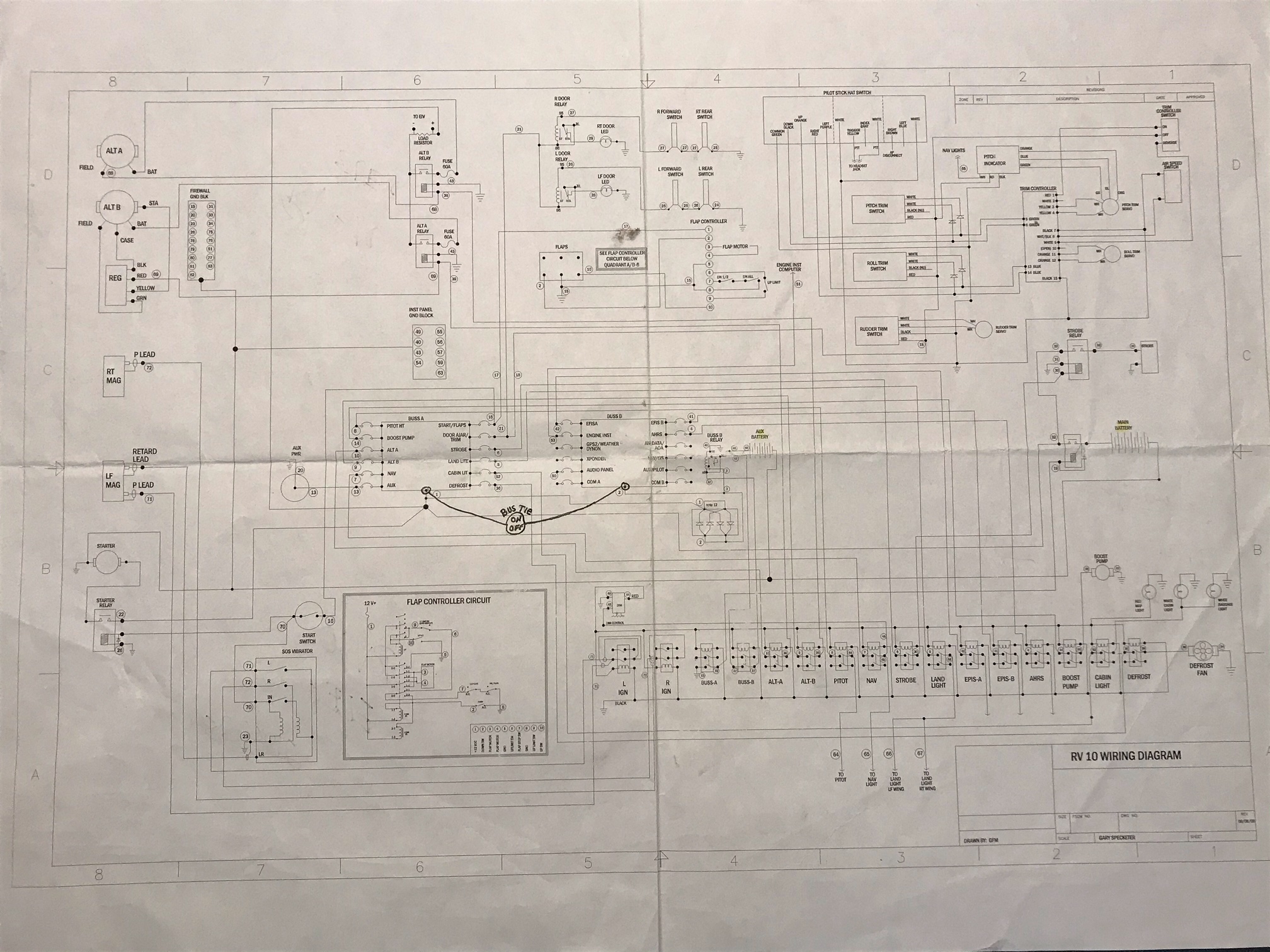
Hey guys I am way in over my head on this forum but a nice man from BandC suggested I try. Attached is the electrical diagram of my recently purchased RV10. It was completed in 2009 and the avionics was switched to a Garmin 900x a year later. My issue is it safe and operationally sound. It is an X design, if that is familiar. Apparently the builder added a bus tie in order to bypass a diode bridge rectifier type because the draw to recharge the Aux Battery, 2 wheel chair batteries 7Ah 12v wired in series reduced the essential bus voltage to 12.6v. This bus tie when on,boosts both busses back to 13.6v. Is this how it was meant to be run?Additionally with both alternators on, the displayed alternator amperage seems to be all over the scale; sometimes 45-50 amps when the airplane has most accessories off. Feeding both alternators into a single âbus barâ seems to cause issues and is that safe?Therefore itâs been recommended that I swap out the Stby Alt for a 60A PP alternator and just use it as the primary power source. My preference would be going to a Z plan where each alternator powers its own bus but Iâve been advised against that. The good news is my A&P figured out the shunt had not been changed per Garmin install instructions, a [url=x-apple-data-detectors://0]100A[/url] 50 milivolts currently on order.Sorry for the length of this & the formatting issues. [img]cid:6752740E-5AA5-45C2-8517-DB2B2E3E319D-L0-001[/img]
| | - The Matronics AeroElectric-List Email Forum - | | | Use the List Feature Navigator to browse the many List utilities available such as the Email Subscriptions page, Archive Search & Download, 7-Day Browse, Chat, FAQ, Photoshare, and much more:
http://www.matronics.com/Navigator?AeroElectric-List |
|
| Description: |
|
| Filesize: |
898.66 KB |
| Viewed: |
6158 Time(s) |
|
|
|
| Back to top |
|
 |
Ceengland
Joined: 11 Oct 2020
Posts: 379
Location: MS
|
| Posted: Sun Jan 10, 2021 6:50 am Post subject: RV10 Electrical Issue (w/ Format Clean Up) |
|
|
On Sun, Jan 10, 2021 at 8:14 AM Robert L. Nuckolls, III <nuckolls.bob(at)aeroelectric.com (nuckolls.bob(at)aeroelectric.com)> wrote:
| Quote: | At 06:54 AM 1/9/2021, you wrote:
| Quote: | | Hey guys I am way in over my head on this forum but a nice man from BandC suggested I try. Attached is the electrical diagram of my recently purchased RV10. It was completed in 2009 and the avionics was switched to a Garmin 900x a year later. My issue is it safe and operationally sound. It is an X design, if that is familiar. |
snipped
| Quote: | | Additionally with both alternators on, the displayed alternator amperage seems to be all over the scale; sometimes 45-50 amps when the airplane has most accessories off. Feeding both alternators into a single ââ¬Åbus barâ⬠seems to cause issues and is that safe? |
  snipped
 Bob . . .
|
I couldn't see the diagram, but the 'all over the place' alternator amperage suggests issues with the shunt's wiring. My (purchased) RV6Â had inline fuse holders for glass fuses to 'protect' the sense lines (protect in quotes because the fuses were somewhere near the middle of the wire runs). The flaky contact between the cheezy fuse holders and the fuses caused amperage readings to be... 'all over the place'. Just one place to look, to isolate your random current readings.
Charlie
| | - The Matronics AeroElectric-List Email Forum - | | | Use the List Feature Navigator to browse the many List utilities available such as the Email Subscriptions page, Archive Search & Download, 7-Day Browse, Chat, FAQ, Photoshare, and much more:
http://www.matronics.com/Navigator?AeroElectric-List |
|
_________________
Charlie |
|
| Back to top |
|
|
jluckey(at)pacbell.net
Guest
|
| Posted: Sun Jan 10, 2021 10:32 am Post subject: RV10 Electrical Issue (w/ Format Clean Up) |
|
|
In the email I received there was no drawing attached. Could someone re-post the drawing file? Or send it to me directly.
In fact, I only see Bob's & Charlie's replies, not the original post. That seems weird....
-Jeff
On Sunday, January 10, 2021, 06:59:46 AM PST, Charlie England <ceengland7(at)gmail.com> wrote:
On Sun, Jan 10, 2021 at 8:14 AM Robert L. Nuckolls, III <nuckolls.bob(at)aeroelectric.com (nuckolls.bob(at)aeroelectric.com)> wrote:
| Quote: | At 06:54 AM 1/9/2021, you wrote:
| Quote: | | Hey guys I am way in over my head on this forum but a nice man from BandC suggested I try. Attached is the electrical diagram of my recently purchased RV10. It was completed in 2009 and the avionics was switched to a Garmin 900x a year later. My issue is it safe and operationally sound. It is an X design, if that is familiar. |
snipped
| Quote: | | Additionally with both alternators on, the displayed alternator amperage seems to be all over the scale; sometimes 45-50 amps when the airplane has most accessories off. Feeding both alternators into a single ââ¬Åbus barâ⬠seems to cause issues and is that safe? |
snipped
Bob . . .
|
I couldn't see the diagram, but the 'all over the place' alternator amperage suggests issues with the shunt's wiring. My (purchased) RV6 had inline fuse holders for glass fuses to 'protect' the sense lines (protect in quotes because the fuses were somewhere near the middle of the wire runs). The flaky contact between the cheezy fuse holders and the fuses caused amperage readings to be... 'all over the place'. Just one place to look, to isolate your random current readings.
Charlie
| | - The Matronics AeroElectric-List Email Forum - | | | Use the List Feature Navigator to browse the many List utilities available such as the Email Subscriptions page, Archive Search & Download, 7-Day Browse, Chat, FAQ, Photoshare, and much more:
http://www.matronics.com/Navigator?AeroElectric-List |
|
|
|
| Back to top |
|
|
Ceengland
Joined: 11 Oct 2020
Posts: 379
Location: MS
|
| Posted: Sun Jan 10, 2021 11:16 am Post subject: RV10 Electrical Issue (w/ Format Clean Up) |
|
|
Hi Jeff,
I never saw the original, either. Since it doesn't show up in the forum format either, I wonder if it went direct to Bob.
However.... I get the list via individual emails, and I *frequently* see replies to posts for which I never got the original. Occasionally, I'll find the original in my gmail spam/junk folders, but often the only way I see them is to look at the forum version. I've assumed that the cause is glitches in the multi-format distribution methods required, but I've never pushed the question to Matt (list owner).
Charlie
On 1/10/2021 12:27 PM, Jeff Luckey wrote:
| Quote: | In the email I received there was no drawing attached. Could someone re-post the drawing file? Or send it to me directly.
In fact, I only see Bob's & Charlie's replies, not the original post. That seems weird....
-Jeff
On Sunday, January 10, 2021, 06:59:46 AM PST, Charlie England <ceengland7(at)gmail.com> (ceengland7(at)gmail.com) wrote:
On Sun, Jan 10, 2021 at 8:14 AM Robert L. Nuckolls, III <nuckolls.bob(at)aeroelectric.com (nuckolls.bob(at)aeroelectric.com)> wrote:
| Quote: | At 06:54 AM 1/9/2021, you wrote:
| Quote: | | Hey guys I am way in over my head on this forum but a nice man from BandC suggested I try. Attached is the electrical diagram of my recently purchased RV10. It was completed in 2009 and the avionics was switched to a Garmin 900x a year later. My issue is it safe and operationally sound. It is an X design, if that is familiar. |
snipped
| Quote: | | Additionally with both alternators on, the displayed alternator amperage seems to be all over the scale; sometimes 45-50 amps when the airplane has most accessories off. Feeding both alternators into a single ââ¬Åbus barâ⬠seems to cause issues and is that safe? |
  snipped
 Bob . . .
|
I couldn't see the diagram, but the 'all over the place' alternator amperage suggests issues with the shunt's wiring. My (purchased) RV6Â had inline fuse holders for glass fuses to 'protect' the sense lines (protect in quotes because the fuses were somewhere near the middle of the wire runs). The flaky contact between the cheezy fuse holders and the fuses caused amperage readings to be... 'all over the place'. Just one place to look, to isolate your random current readings.
Charlie
|
 Virus-free. www.avast.com [url=#DAB4FAD8-2DD7-40BB-A1B8-4E2AA1F9FDF2] [/url] Virus-free. www.avast.com [url=#DAB4FAD8-2DD7-40BB-A1B8-4E2AA1F9FDF2] [/url]
| | - The Matronics AeroElectric-List Email Forum - | | | Use the List Feature Navigator to browse the many List utilities available such as the Email Subscriptions page, Archive Search & Download, 7-Day Browse, Chat, FAQ, Photoshare, and much more:
http://www.matronics.com/Navigator?AeroElectric-List |
|
_________________
Charlie |
|
| Back to top |
|
|
jluckey(at)pacbell.net
Guest
|
| Posted: Sun Jan 10, 2021 1:05 pm Post subject: RV10 Electrical Issue (w/ Format Clean Up) |
|
|
BobN - Thanks for the drawing.
Charlie - I interact with the List in exactly the same way & have the same experiences you detailed. Good to know it's not just me.
Does anyone know in what part of the country the original poster is located?
-Jeff
On Sunday, January 10, 2021, 11:25:31 AM PST, Charlie England <ceengland7(at)gmail.com> wrote:
Hi Jeff, I never saw the original, either. Since it doesn't show up in the forum format either, I wonder if it went direct to Bob. However.... I get the list via individual emails, and I *frequently* see replies to posts for which I never got the original. Occasionally, I'll find the original in my gmail spam/junk folders, but often the only way I see them is to look at the forum version. I've assumed that the cause is glitches in the multi-format distribution methods required, but I've never pushed the question to Matt (list owner). Charlie On 1/10/2021 12:27 PM, Jeff Luckey wrote:
In the email I received there was no drawing attached. Could someone re-post the drawing file? Or send it to me directly.
In fact, I only see Bob's & Charlie's replies, not the original post. That seems weird....
-Jeff
On Sunday, January 10, 2021, 06:59:46 AM PST, Charlie England <ceengland7(at)gmail.com> (ceengland7(at)gmail.com) wrote:
On Sun, Jan 10, 2021 at 8:14 AM Robert L. Nuckolls, III <nuckolls.bob(at)aeroelectric.com (nuckolls.bob(at)aeroelectric.com)> wrote:
| Quote: | At 06:54 AM 1/9/2021, you wrote: | Quote: | | Hey guys I am way in over my head on this forum but a nice man from BandC suggested I try. Attached is the electrical diagram of my recently purchased RV10. It was completed in 2009 and the avionics was switched to a Garmin 900x a year later. My issue is it safe and operationally sound. It is an X design, if that is familiar. |
snipped | Quote: | | Additionally with both alternators on, the displayed alternator amperage seems to be all over the scale; sometimes 45-50 amps when the airplane has most accessories off. Feeding both alternators into a single ââ¬Åbus barâ⬠seems to cause issues and is that safe? |
snipped
Bob . . .
|
I couldn't see the diagram, but the 'all over the place' alternator amperage suggests issues with the shunt's wiring. My (purchased) RV6 had inline fuse holders for glass fuses to 'protect' the sense lines (protect in quotes because the fuses were somewhere near the middle of the wire runs). The flaky contact between the cheezy fuse holders and the fuses caused amperage readings to be... 'all over the place'. Just one place to look, to isolate your random current readings.
Charlie
Virus-free. www.avast.com [url=#DAB4FAD8-2DD7-40BB-A1B8-4E2AA1F9FDF2] [/url]
| | - The Matronics AeroElectric-List Email Forum - | | | Use the List Feature Navigator to browse the many List utilities available such as the Email Subscriptions page, Archive Search & Download, 7-Day Browse, Chat, FAQ, Photoshare, and much more:
http://www.matronics.com/Navigator?AeroElectric-List |
|
|
|
| Back to top |
|
|
user9253
Joined: 28 Mar 2008
Posts: 1908
Location: Riley TWP Michigan
|
| Posted: Sun Jan 10, 2021 7:19 pm Post subject: Re: RV10 Electrical Issue (w/ Format Clean Up) |
|
|
The email problems can be avoided by reading posts here:

http://forums.matronics.com/viewforum.php?f=3

The OP is from Virginia.
| | - The Matronics AeroElectric-List Email Forum - | | | Use the List Feature Navigator to browse the many List utilities available such as the Email Subscriptions page, Archive Search & Download, 7-Day Browse, Chat, FAQ, Photoshare, and much more:
http://www.matronics.com/Navigator?AeroElectric-List |
|
_________________
Joe Gores |
|
| Back to top |
|
|
Ceengland
Joined: 11 Oct 2020
Posts: 379
Location: MS
|
| Posted: Sun Jan 10, 2021 8:00 pm Post subject: RV10 Electrical Issue (w/ Format Clean Up) |
|
|
We're aware, but some of us just prefer email delivery.
Sent from BlueMail
On Jan 10, 2021, at 9:31 PM, user9253 <fransew(at)gmail.com (fransew(at)gmail.com)> wrote:
| | - The Matronics AeroElectric-List Email Forum - | | | Use the List Feature Navigator to browse the many List utilities available such as the Email Subscriptions page, Archive Search & Download, 7-Day Browse, Chat, FAQ, Photoshare, and much more:
http://www.matronics.com/Navigator?AeroElectric-List |
|
_________________
Charlie |
|
| Back to top |
|
|
rick(at)beebe.org
Guest
|
| Posted: Sun Jan 10, 2021 9:36 pm Post subject: RV10 Electrical Issue (w/ Format Clean Up) |
|
|
On 1/10/2021 7:06 PM, WILLIAM BOOTH wrote:
| Quote: | I can add after 6 months of frustration I have learned a lot about my
electrical system. Â The shunt off of the alternators is incorrect and
will be replaced this week. Â The battery shunt appears to be off by a
factor of 2.5. The Garmin draw with only the battery on and both PFDâs
tested at 7amps draw while the Garmin displayed 17 amps draw. Â This
implies to me that it needs a 250a and 50mV shunt. Â I plan on
contacting Garmin this week to determine their requirements.
|
Garmin specs a 100amp 50mV shunt. Certainly if the shunt and efis
settings don't match you'll get inaccurate readings. 7 amps sounds about
right to me. Also, I saw the previous comment about fuses in the middle
of the sense lines. Excess resistance there will also affect the
readings. Fuses are a good idea but they should be right at the shunt. I
used pico fuses to avoid issues with a fuse holder.
--Rick
| | - The Matronics AeroElectric-List Email Forum - | | | Use the List Feature Navigator to browse the many List utilities available such as the Email Subscriptions page, Archive Search & Download, 7-Day Browse, Chat, FAQ, Photoshare, and much more:
http://www.matronics.com/Navigator?AeroElectric-List |
|
|
|
| Back to top |
|
|
Ceengland
Joined: 11 Oct 2020
Posts: 379
Location: MS
|
| Posted: Mon Jan 11, 2021 8:07 am Post subject: RV10 Electrical Issue (w/ Format Clean Up) |
|
|
On 1/11/2021 7:15 AM, Robert L. Nuckolls, III wrote:
| Quote: | | Quote: | Garmin specs a 100amp 50mV shunt. Certainly if the shunt and efis settings don't match you'll get inaccurate readings. 7 amps sounds about right to me. Also, I saw the previous comment about fuses in the middle of the sense lines. Excess resistance there will also affect the readings. Fuses are a good idea but they should be right at the shunt. I used pico fuses to avoid issues with a fuse holder.
\ |
There is virtually zero current flowing in the sense
leads off a shunt to the display. Fuses and connectors
in these leads do not adversely affect calibration.
Bob . . .
|
But varying resistance does; at least with a Dynon EMS D-10. My plane has really cheesy inline fuse holders for the little glass instrument fuses. I was seeing large but inconsistent discharge indications. When I reached under the panel and pulled on the inline fuse holders, current readings would return to normal. After a few days or weeks, random high current readings would show up again, and the cure would be the same.
I didn't attempt to 'instrument' the sense leads to prove the diagnosis, but as you know, this troubleshooting technique has been pretty effective since we started thumping vacuum tubes.
Charlie
Virus-free. www.avast.com [url=#DAB4FAD8-2DD7-40BB-A1B8-4E2AA1F9FDF2] [/url]
| | - The Matronics AeroElectric-List Email Forum - | | | Use the List Feature Navigator to browse the many List utilities available such as the Email Subscriptions page, Archive Search & Download, 7-Day Browse, Chat, FAQ, Photoshare, and much more:
http://www.matronics.com/Navigator?AeroElectric-List |
|
_________________
Charlie |
|
| Back to top |
|
|
pilotgary99(at)gmail.com
Guest
|
| Posted: Mon Jan 11, 2021 5:31 pm Post subject: RV10 Electrical Issue (w/ Format Clean Up) |
|
|
Was written...
| Quote: | | Hey guys I am way in over my head on this forum but a nice man from BandC suggested I try. Attached is the electrical diagram of my recently purchased RV10. It was completed in 2009 and the avionics was switched to a Garmin 900x a year later. My issue is it safe and operationally sound. It is an X design, if that is fa |
I missed your original post, but I feel the same way about being a newbie. Cannot understand why aircraft electronics are hard for me. I can wire 125v circuits with my eyes closed. Apprehensive about wiring my EAB aircraft.
On Sun, Jan 10, 2021 at 8:15 AM Robert L. Nuckolls, III <nuckolls.bob(at)aeroelectric.com (nuckolls.bob(at)aeroelectric.com)> wrote:
| Quote: | At 06:54 AM 1/9/2021, you wrote:
| Quote: | | Hey guys I am way in over my head on this forum but a nice man from BandC suggested I try. Attached is the electrical diagram of my recently purchased RV10. It was completed in 2009 and the avionics was switched to a Garmin 900x a year later. My issue is it safe and operationally sound. It is an X design, if that is familiar. |
 That's a REALLY busy electrical system . . .
| Quote: | | Apparently the builder added a bus tie in order to bypass a diode bridge rectifier type because the draw to recharge the Aux Battery, 2 wheel chair batteries 7Ah 12v wired in series reduced the essential bus voltage to 12.6v. This bus tie when on,boosts both busses back to 13.6v. Is this how it was meant to be run? |
 The thought processes behind this architecture cannot
 be know to us unless it's documented somewhere. The
 system depicted has features that are
| Quote: | | Additionally with both alternators on, the displayed alternator amperage seems to be all over the scale; sometimes 45-50 amps when the airplane has most accessories off. Feeding both alternators into a single ââ¬Åbus barâ⬠seems to cause issues and is that safe? |
 Why run both at the same time?
| Quote: | Therefore it's been recommended that I swap out the Stby Alt for a 60A PP alternator and just use it as the primary power source. My preference would be going to a Z plan where each alternator powers its own bus but I've been advised against that. The good news is my A&P figured out the shunt had not been changed per Garmin install instructions, a 100A 50 milivolts currently on order.
|
 Aside from the things you've described here has
 this system been flying 'successfully' since 2009?
 Unless the seller offered the equivalent of a pilots
 operating handbook for the system, you're kinda
 stuck with second guessing the builder's original
 design goals.Â
 The builder spent a lot of time providing a good
 drawing of the wiring which is good. But the arrangement
 makes it difficult to sort out exactly how this
 system is supposed to function. Wiring for
 bridge rectifier is curious . . . it shows all
 four terminals tied together which negates its
 function as a diode array.
 Changing this system to conform to a Z-figure
 would be a BIG task. What are your plans/expectations
 for getting the airplane flyable?
 Bob . . .
 Un impeachable logic: George Carlin asked, "If black boxes
 survive crashes, why don't they make the whole airplane
 out of that stuff?"
|
| | - The Matronics AeroElectric-List Email Forum - | | | Use the List Feature Navigator to browse the many List utilities available such as the Email Subscriptions page, Archive Search & Download, 7-Day Browse, Chat, FAQ, Photoshare, and much more:
http://www.matronics.com/Navigator?AeroElectric-List |
|
|
|
| Back to top |
|
|
Mauledriver(at)nc.rr.com
Guest
|
| Posted: Tue Jan 12, 2021 4:26 am Post subject: RV10 Electrical Issue (w/ Format Clean Up) |
|
|
On 1/11/2021 8:26 PM, Gary Wold wrote:
| Quote: | Was written...
| Quote: | | Hey guys I am way in over my head on this forum but a nice man from BandC suggested I try. Attached is the electrical diagram of my recently purchased RV10. It was completed in 2009 and the avionics was switched to a Garmin 900x a year later. My issue is it safe and operationally sound. It is an X design, if that is fa |
I missed your original post, but I feel the same way about being a newbie. Cannot understand why aircraft electronics are hard for me. I can wire 125v circuits with my eyes closed. Apprehensive about wiring my EAB aircraft.
|
I'm not a complete newbie but an amateur that has installed a Z-14 in an RV10 and flown it for 10+ years and 1,000+ hours.
Untangling someone else's pride and joy versus working on your own electrical system from the ground up appears to be 2 different tasks. In this case the system is well documented but the design intent is unknown. That's half good but challenging.
If you are DIYing your electrical system one of the best things you can do is read up the stuff presented here and decide to implement one of the 'Z' designs documented here. Then implement it without modifying it here and there to achieve some capability you think you need. Why not? Because that capability has most likely been considered, hashed out, possibly tested, and then either implemented in the appropriate Z design or discarded as not needed or wrong headed. If you select the right Z figure and stick with it, you'll do well. Some very good heads have spent a lot of time and effort honing these designs down into very serviceable solutions - all under the guidance and leadership of Mr Nuckulls.
Doing a Z design 'as-is' will simplify things greatly. Me, I think I'm going to write up a 1 pager on my design intent and how it should be operated. Right now that just in my head.
Have Fun!

This email has been checked for viruses by Avast antivirus software.
www.avast.com [url=#DAB4FAD8-2DD7-40BB-A1B8-4E2AA1F9FDF2] [/url]
| | - The Matronics AeroElectric-List Email Forum - | | | Use the List Feature Navigator to browse the many List utilities available such as the Email Subscriptions page, Archive Search & Download, 7-Day Browse, Chat, FAQ, Photoshare, and much more:
http://www.matronics.com/Navigator?AeroElectric-List |
|
|
|
| Back to top |
|
|
user9253
Joined: 28 Mar 2008
Posts: 1908
Location: Riley TWP Michigan
|
| Posted: Tue Jan 12, 2021 8:38 am Post subject: Re: RV10 Electrical Issue (w/ Format Clean Up) |
|
|
What appear to be relays in the lower right corner are actually illuminated switches.


I do not see any over voltage protection.


While cranking the engine, if the bus tie switch is closed and if bus B switch is closed,

then the aux battery will help crank the engine.  Are the wires big enough to

handle the current?  The solution is to eliminate the bus tie switch.  So what

if bus B is one volt less than Bus A?  A Schottky diode will not drop as much

voltage and will not get as hot.


Alternators A and B have their labels reversed.


The strobe circuit needs to be protected by a fuse.


Connecting both alternators to one current shunt is not necessarily unsafe unless the shunt fails.

Consider using individual hall effect current sensors.

If the alternators do not play well with each other, the simple solution is to only have one on at a time.


If the original builder practiced good workmanship, I would not rewire the airplane.
| | - The Matronics AeroElectric-List Email Forum - | | | Use the List Feature Navigator to browse the many List utilities available such as the Email Subscriptions page, Archive Search & Download, 7-Day Browse, Chat, FAQ, Photoshare, and much more:
http://www.matronics.com/Navigator?AeroElectric-List |
|
_________________
Joe Gores |
|
| Back to top |
|
|
Tim Olson
Joined: 25 Jan 2007
Posts: 2871
|
| Posted: Tue Jan 12, 2021 2:07 pm Post subject: RV10 Electrical Issue (w/ Format Clean Up) |
|
|
I would suggest that the battery arrangement in the picture shouldn't have ever
been part of the cranking circuit.  I say this because it looks like that was
a copy of my aux battery config, of which I was the first RV-10 to put them
in that location. It looks like the liked my location, liked some of the
configuration, but then if they tried in any way to use it for engine cranking,
they took a hard turn and went down a different path than those batteries
would have ever been planned to be used for.
My primary battery is an Odyssey PC925, located in the tail, and it has no
problem cranking the engine all by itself.
People who use PC680's often install 2, in the same rear location, and tie them
together for cranking. You should probably have someone look over
that portion of your electrical system in particular, and just plan to remove
these by the flap torque tube completely from any engine cranking operation.
Tim
On 1/12/2021 3:07 PM, WILLIAM BOOTH wrote:
| Quote: | | Quote: | I would like to avoid rewiring if possible.
- Over voltage protection I can resolve with a PP alternator (and change it over to the primary?).
- The batteries to help crank not only are not big enough , but the wires are not big enough. (Picture included.)
- A Schottky diode is a great solution but wiring it like my current one would be incorrect as âIâ understand it. (Picture included.)
- Great catch on the mislabeled alternators; I saw that too.
- The Hall effect current sensor; is that a directional flow item, like a diode?
- Yes on the one at a time and only keep the other one for STANDBY use.
William Booth
|
| Quote: |
Sent from my iPad
| Quote: | On Jan 12, 2021, at 11:42 AM, user9253 <fransew(at)gmail.com> (fransew(at)gmail.com) wrote:
--> AeroElectric-List message posted by: "user9253" <fransew(at)gmail.com> (fransew(at)gmail.com)
What appear to be relays in the lower right corner are actually illuminated switches.
I do not see any over voltage protection.
While cranking the engine, if the bus tie switch is closed and if bus B switch is closed,
then the aux battery will help crank the engine. Are the wires big enough to
handle the current? The solution is to eliminate the bus tie switch. So what
if bus B is one volt less than Bus A? A Schottky diode will not drop as much
voltage and will not get as hot.
Alternators A and B have their labels reversed.
The strobe circuit needs to be protected by a fuse.
Connecting both alternators to one current shunt is not necessarily unsafe unless the shunt fails.
Consider using individual hall effect current sensors.
If the alternators do not play well with each other, the simple solution is to only have one on at a time.
If the original builder practiced good workmanship, I would not rewire the airplane.
--------
Joe Gores
Read this topic online here:
http://forums.matronics.com/viewtopic.php?p=500156#500156
|
====================================
====================================
====================================
====================================
====================================
|
|
| | - The Matronics AeroElectric-List Email Forum - | | | Use the List Feature Navigator to browse the many List utilities available such as the Email Subscriptions page, Archive Search & Download, 7-Day Browse, Chat, FAQ, Photoshare, and much more:
http://www.matronics.com/Navigator?AeroElectric-List |
|
|
|
| Back to top |
|
|
rbs80
Joined: 30 Nov 2020
Posts: 10
Location: Virginia
|
| Posted: Tue Jan 12, 2021 2:19 pm Post subject: RV10 Electrical Issue (w/ Format Clean Up) |
|
|
BTW what is the purpose of the diode, how is it used and how does the electricity flow thru it?
William Booth
| Quote: | On Jan 12, 2021, at 11:42 AM, user9253 <fransew(at)gmail.com> wrote:

What appear to be relays in the lower right corner are actually illuminated switches.
I do not see any over voltage protection.
While cranking the engine, if the bus tie switch is closed and if bus B switch is closed,
then the aux battery will help crank the engine. Are the wires big enough to
handle the current? The solution is to eliminate the bus tie switch. So what
if bus B is one volt less than Bus A? A Schottky diode will not drop as much
voltage and will not get as hot.
Alternators A and B have their labels reversed.
The strobe circuit needs to be protected by a fuse.
Connecting both alternators to one current shunt is not necessarily unsafe unless the shunt fails.
Consider using individual hall effect current sensors.
If the alternators do not play well with each other, the simple solution is to only have one on at a time.
If the original builder practiced good workmanship, I would not rewire the airplane.
--------
Joe Gores
Read this topic online here:
http://forums.matronics.com/viewtopic.php?p=500156#500156
|
| | - The Matronics AeroElectric-List Email Forum - | | | Use the List Feature Navigator to browse the many List utilities available such as the Email Subscriptions page, Archive Search & Download, 7-Day Browse, Chat, FAQ, Photoshare, and much more:
http://www.matronics.com/Navigator?AeroElectric-List |
|
|
|
| Back to top |
|
|
user9253
Joined: 28 Mar 2008
Posts: 1908
Location: Riley TWP Michigan
|
| Posted: Tue Jan 12, 2021 4:00 pm Post subject: Re: RV10 Electrical Issue (w/ Format Clean Up) |
|
|
Think of the diode as a one way check valve.  It allows current to

flow from bus A to bus B, but not in the opposite direction.
| | - The Matronics AeroElectric-List Email Forum - | | | Use the List Feature Navigator to browse the many List utilities available such as the Email Subscriptions page, Archive Search & Download, 7-Day Browse, Chat, FAQ, Photoshare, and much more:
http://www.matronics.com/Navigator?AeroElectric-List |
|
_________________
Joe Gores |
|
| Back to top |
|
|
rbs80
Joined: 30 Nov 2020
Posts: 10
Location: Virginia
|
| Posted: Tue Jan 12, 2021 6:07 pm Post subject: RV10 Electrical Issue (w/ Format Clean Up) |
|
|
RE the diode: Specifically why is it needed on this design; how else could the power flow?
Re: Timâs comment on the Aux Batteries; too small and the wires too small too....
I agree it has puzzled me when I first saw it but if buse B is turned on for start I should be ok? That being said how else should it be done? Again safe and sound is the goal.
William Booth
| Quote: | On Jan 12, 2021, at 7:05 PM, user9253 <fransew(at)gmail.com> wrote:

Think of the diode as a one way check valve. It allows current to
flow from bus A to bus B, but not in the opposite direction.
--------
Joe Gores
Read this topic online here:
http://forums.matronics.com/viewtopic.php?p=500172#500172
|
| | - The Matronics AeroElectric-List Email Forum - | | | Use the List Feature Navigator to browse the many List utilities available such as the Email Subscriptions page, Archive Search & Download, 7-Day Browse, Chat, FAQ, Photoshare, and much more:
http://www.matronics.com/Navigator?AeroElectric-List |
|
|
|
| Back to top |
|
|
user9253
Joined: 28 Mar 2008
Posts: 1908
Location: Riley TWP Michigan
|
| Posted: Tue Jan 12, 2021 8:01 pm Post subject: Re: RV10 Electrical Issue (w/ Format Clean Up) |
|
|
Follow the wires from the aux battery, through the bus B relay, to

Bus B, through the bus tie switch, to bus A, to the big dot (junction)

below bus A, to the starter relay, to the starter.

Lots of current will flow through that path.  Prevent it by removing the bus tie switch.

And remove that jumper from the bottom of the diodes (labeled 2)

because it also will conduct starter current.
| | - The Matronics AeroElectric-List Email Forum - | | | Use the List Feature Navigator to browse the many List utilities available such as the Email Subscriptions page, Archive Search & Download, 7-Day Browse, Chat, FAQ, Photoshare, and much more:
http://www.matronics.com/Navigator?AeroElectric-List |
|
_________________
Joe Gores |
|
| Back to top |
|
|
user9253
Joined: 28 Mar 2008
Posts: 1908
Location: Riley TWP Michigan
|
| Posted: Thu Jan 14, 2021 4:38 pm Post subject: Re: RV10 Electrical Issue (w/ Format Clean Up) |
|
|
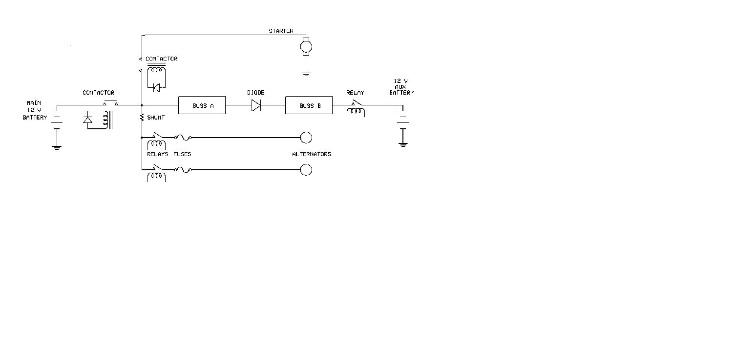
I redrew part of the RV-10 electrical drawing from post #1 to make it easier to read.
| | - The Matronics AeroElectric-List Email Forum - | | | Use the List Feature Navigator to browse the many List utilities available such as the Email Subscriptions page, Archive Search & Download, 7-Day Browse, Chat, FAQ, Photoshare, and much more:
http://www.matronics.com/Navigator?AeroElectric-List |
|
| Description: |
|
| Filesize: |
11.11 KB |
| Viewed: |
5987 Time(s) |
|
_________________
Joe Gores |
|
| Back to top |
|
|
rbs80
Joined: 30 Nov 2020
Posts: 10
Location: Virginia
|
| Posted: Thu Jan 14, 2021 5:36 pm Post subject: RV10 Electrical Issue (w/ Format Clean Up) |
|
|
Thanks again Joe. Iâm soaking this up as best I can. To me it simplifies the system.
I need to research how to read the relay symbology. The relay on the aux batteries: I assume that as long as there is power to the main buses the relay is open but if that power were to fail it closes and provides power from the aux batteries to the essential bus.
William Booth
| | - The Matronics AeroElectric-List Email Forum - | | | Use the List Feature Navigator to browse the many List utilities available such as the Email Subscriptions page, Archive Search & Download, 7-Day Browse, Chat, FAQ, Photoshare, and much more:
http://www.matronics.com/Navigator?AeroElectric-List |
|
|
|
| Back to top |
|
|
user9253
Joined: 28 Mar 2008
Posts: 1908
Location: Riley TWP Michigan
|
| Posted: Thu Jan 14, 2021 6:34 pm Post subject: Re: RV10 Electrical Issue (w/ Format Clean Up) |
|
|
I do not think that the aux battery relay automatically switches on if needed.

It is hard to tell because the drawing is blurry.

But it looks like Bus B switch must be turned on to energize the relay.
| | - The Matronics AeroElectric-List Email Forum - | | | Use the List Feature Navigator to browse the many List utilities available such as the Email Subscriptions page, Archive Search & Download, 7-Day Browse, Chat, FAQ, Photoshare, and much more:
http://www.matronics.com/Navigator?AeroElectric-List |
|
_________________
Joe Gores |
|
| Back to top |
|
|
|
|
You cannot post new topics in this forum
You cannot reply to topics in this forum
You cannot edit your posts in this forum
You cannot delete your posts in this forum
You cannot vote in polls in this forum
You cannot attach files in this forum
You can download files in this forum
|
Powered by phpBB © 2001, 2005 phpBB Group
|

