 |
Matronics Email Lists
Web Forum Interface to the Matronics Email Lists
|
| View previous topic :: View next topic |
| Author |
Message |
nuckolls.bob(at)aeroelect
Guest
|
 Posted: Tue Apr 21, 2020 6:02 pm Post subject: OV B-lead Relay Posted: Tue Apr 21, 2020 6:02 pm Post subject: OV B-lead Relay |
 |
|
| Quote: | | Quote: | | My admittedly sometimes faulty memory of the whole 'load dump' situation two decades ago was that guys were flipping their alt switches/breakers (which controlled the B lead contactor) while the alt was under load, and killing the alt. IIRC, after multiple incidents like that, the OV module/contactor circuit became a lot harder to find in the AEC docs. |
|
Yeah, your memory is correct. The Z24 pot boiled
over when I think only one individual experienced
alternator failure after cycling it. We don't know
how fast the engine was running or what the alternator
loads were . . . you never get that quality of data
from someone pointing a figure at you hollering, "you
alternator killer!"
I think Paul M was a well entrenched advisor to
that faction of RV fans and he was rather antagonistic
to anything 'crowbar'.
| Quote: | | My solution is the He Haw Solution: 'If it hurts when you do that, DON'T DO THAT!' |
Exactly. If the alternator is brought off and
on line at engine idle (standard ops) then
there is no risk.
| Quote: | | Here's my take: If I operate the IR alternator just like it's operated in the car, I'll never have a load dump event. If I use an OV module that is relatively immune to 'false positives', along with a relatively robust B lead contactor, the only penalty I see is carrying a few ounces of extra weight for the contactor. The contactor will never operate unless the regulator has failed (in an OV mode), in which case the 'load dump' issue is already moot. |
That was the spirit and intent of the design
but I failed to include a note precluding random
operations at high rpm. In all fairness, any
alternator should be able to respond safely
to on/off commands under any speed and load
conditions.
| Quote: | | This lets me use an off the shelf, *very inexpensive*, available at any auto supply, alternator. It won't be as reliable as a B&C, but based on anecdotal evidence from RV-x owners, a *lot* more reliable than a Plane Power. And I'll have about $500 left over to buy fuel. (Replacement alts, if ever needed, will be free.) If I do have to replace the alt while away from home, no mod to the alt is needed, and replacement can happen on the ramp with only a couple of wrenches. |
Is PlanePower having issues? I think they
were bought out by a company that shall
remain nameless. Has their craftsmanship
suffered?
| Quote: | | I have had several different 'lives' as an electronics tech, from home electronics to pro sound, to industrial gear. Even though I'd consider myself to be well above average in qualifications, I trust an 'as-built' alternator to be more reliable than one that I've modded. |
YEeaahh . . . with reservations. The recent
Kitplanes article we've discussed here is
a rather benign operation . . . with profound
benefit.
| Quote: | | My opinion is that if any update is made, it would be to redesign the OV module to reduce the risk of 'false positive' nuisance trips, and retain the B lead relay. Perhaps do a little testing on whether a single contact automotive cube relay can reliably open the B lead, *once*, as Bob Noffs mentioned, and treat the relay as if it's a fusible link. |
If we combined the crowbar feature with
the 200A 'cube' relay, the ov sense could
be a microcontroller that waits until the
relay contacts are sensed to be open before
triggering the FET. That would reduce abuse
to the relay to insignificance for both
an OV shutdown -AND- the normal on/off commands
at ANY rpm.
To be sure, MOST modern alternators including
rebuilds should be able to stand off the load
dump spike.
| Quote: | | Realistically, if the OV module fires at ~16V, how much energy is really there? How much delay will there be from hitting the voltage threshold to the contacts opening? If we used a 100A cube relay (which *should*, by definition, be able to actively control a 100A load), will it really be stressed by 60-70 amps at ~20V? Or will the voltage (and energy) be much higher by the time the contacts actually start to open? I realize that voltage will spike upward as the contacts separate, but will it be bad enough in a 'one shot' environment to weld the contacts? |
Yeah, an ov trip condition is asserted when
bus voltage rises above 16v for say 500 mS.
By this time, the energy 'spring' in the
failed alternator is really wound up pretty
good. I've observed field voltages on the
order of 1 to 2 volts for alternators carrying
a normal running load at cruise rpm. So
if you suddenly increase that voltage to 15v,
the 'spring' starts winding rapidly while held
at bay by the battery+system loads.
This is the special condition that might be
handled nicely with a fat-FET and relay.
. . . I'd want to do some studies on the
alternator test stand before running very far down
that rabbit hole.
But FOR SURE . . . a fat-FET and diode would
be a piece of cake because there's no timing
to worry about and the b-lead never rises very
far given that it's loaded down by the ship's
battery. Best yet, no concerns for keeping your
contacts out of the fire.
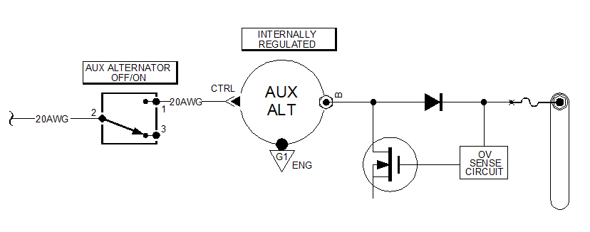
For an AUX alternator in the 20-30A class,
the diode/fet crowbar need not be very
beefy. Maybe not so attractive for MAIN
alternators in the 60A+ class. Voltage
drop across the diode becomes an energy
management issue.
There was a time that Cessna was using
some fat diodes in the alternator b-leads
to orchestrate an alternator failure
sensor some guy at Cessna dreamed up . . .
not me!
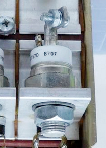
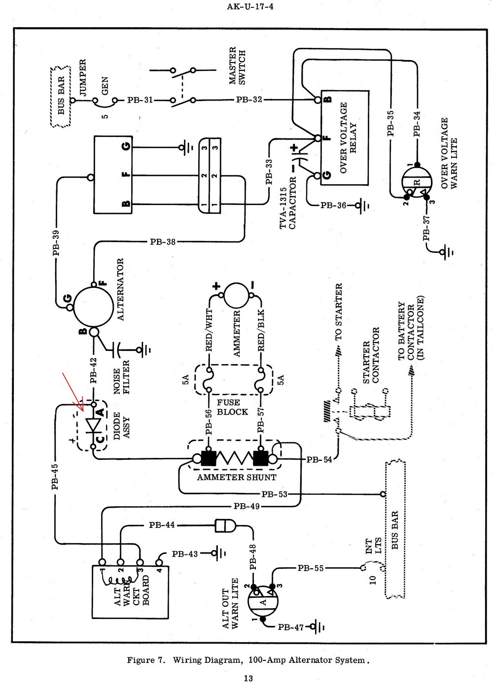
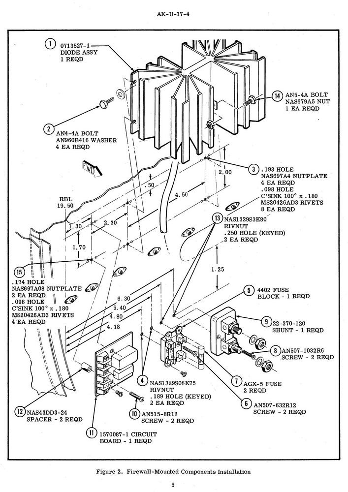
Here are some excerpts from a kit I wrote to
put a 100A alternator on a USAF U17. That
diode dropped about 0.9V at 100A for a
dissipation the order of 90W. Needless
to say, the heatsink was impressive. I
seem to recall we did a similar thing
on the C337. Had to dig pretty deep into
the archives for those images. Wrote that
kit in 1968!
A Schottky b-lead diode for a 30A alternator
would be much more manageable.
Bob . . .
| | - The Matronics AeroElectric-List Email Forum - | | | Use the List Feature Navigator to browse the many List utilities available such as the Email Subscriptions page, Archive Search & Download, 7-Day Browse, Chat, FAQ, Photoshare, and much more:
http://www.matronics.com/Navigator?AeroElectric-List |
|
| Description: |
|
| Filesize: |
62.92 KB |
| Viewed: |
4110 Time(s) |
|
| Description: |
|
| Filesize: |
207.14 KB |
| Viewed: |
4110 Time(s) |
|
| Description: |
|
| Filesize: |
179.62 KB |
| Viewed: |
4110 Time(s) |
|
| Description: |
|
| Filesize: |
62.45 KB |
| Viewed: |
4110 Time(s) |
|
|
|
| Back to top |
|
 |
nuckolls.bob(at)aeroelect
Guest
|
| Posted: Tue Apr 21, 2020 6:16 pm Post subject: OV B-lead Relay |
|
|
At 02:25 PM 4/21/2020, you wrote:
| Quote: | --> AeroElectric-List message posted by: "Dan Fritz" <Dfritzj(at)yahoo.com>
One of the things I've always wondered about with Z-24 was the
impact of the B-lead contactor opening when the field switch
is opened. This appears to negate any positive influence of
having a progressive switch for the master contactor and field power. |
Not sure how . . . the progressive transfer is an
emulation of the 'split rocker' that simply prevents
alternator operations without a battery on line.
Adding the relay-crowbar ov control system doesn't
negate that design goal.
| Quote: | What do you all think of the adjustment propose in the attached to
Z-24 to re-introduce the goodness of the progressive switch while
keeping the full protection offered by Z-24. |
I'm not seeing the proposed advantage. Remember
that the "F" terminal on an internally regulated
alternator is simply a control lead that talks
to the internal regulator. Once the regulator
has failed, it matters not what voltage appears
at the "F" terminal . . . the b-lead is straining
to take off for the moon.
| Quote: | One could also consider putting a TVS across the B-lead between the B-lead
contactor and the alternator in an attempt to save the regulator
if a nuisance trip of the Overvoltage protection were to take place. |
Remember that TVS (transient voltage suppressor) is
designed to take on fairly large currents for a very
SHORT period of time. In Z24 the alternator cannot
be shut down hence this is no longer a transient
event but a uncontrolled runaway that will continue
until the field windings burn in two.
| Quote: | | P.S. did this "old school" with whiteout and a pencil, excuse the messiness... |
fine pencil work . . .
Bob . . .
| | - The Matronics AeroElectric-List Email Forum - | | | Use the List Feature Navigator to browse the many List utilities available such as the Email Subscriptions page, Archive Search & Download, 7-Day Browse, Chat, FAQ, Photoshare, and much more:
http://www.matronics.com/Navigator?AeroElectric-List |
|
|
|
| Back to top |
|
|
Dan Fritz
Joined: 02 Apr 2020
Posts: 16
|
| Posted: Tue Apr 21, 2020 7:45 pm Post subject: Re: OV B-lead Relay |
|
|
Bob,

Thanks for the explanation on the B-lead contactor and progressive field switch.


I like the direction you're going with the B-lead crowbar solution.  Seems like it could make the OV event much less spectacular and potentially even save a few alternators from load dumps in nuisance trip situations.  It also saves the effort to modify the alternator to eliminate the internal regulator and keeps the Autozone replacement alternator from taking up too much $time$.


That said, you've piqued my interest, I'll have to dig into my alternator to see what I've got lurking inside and determine if I want to take it on.  Sounds like there was a recent Kitplanes article that outlines a simple mod, can anyone point me to a link?


thanks,

Dan
| | - The Matronics AeroElectric-List Email Forum - | | | Use the List Feature Navigator to browse the many List utilities available such as the Email Subscriptions page, Archive Search & Download, 7-Day Browse, Chat, FAQ, Photoshare, and much more:
http://www.matronics.com/Navigator?AeroElectric-List |
|
|
|
| Back to top |
|
|
finn.lassen(at)verizon.ne
Guest
|
| Posted: Wed Apr 22, 2020 6:10 am Post subject: OV B-lead Relay |
|
|
On 4/21/2020 8:21 PM, Robert L. Nuckolls, III wrote:
| Quote: | �� But given the ease with which the alternator
�� can be modified into a real 'aircraft'
�� part, any notions of a Z24 update are not
�� so interesting.
|
That's what I was going to do and only have a fuseable link between B+
and battery.
But a remark of "other possible alternator failure mode" made me
consider putting a 80A "cube" relay in that path.
I assumed that that "other failure mode" would be a shorted rectifier
diode (drawing current from battery). Not sure of the likelihood of such
a failure. In my experience diodes fail open (and zeners fail shorted).
I really don't like a contactor because of weight and the current it
draws.� The 80A relay has a 85 ohm coil resistance. and the contactor I
have 15 ohms. 2 W vs 12 W.
I should mention I'm putting a Mazda 13B (Renesis) in an RV-4. So in a
battery-only (no alternator) situation, it's important to be able to
shred all loads that are not required to keep the engine running and I'm
designing to electrical system accordingly. The manufacturer (RWS) of
the engine controller recommends engine-essential item be powered
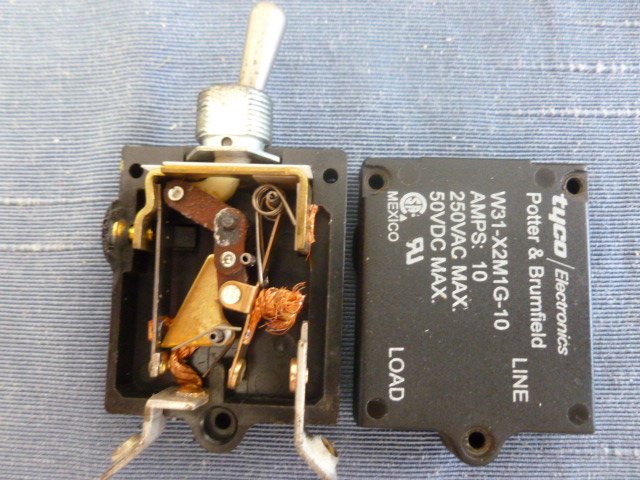
directly from battery (via one switch/breaker). However, having
dissected a failed (open) W31- breaker/switch, I'll double that with a
pull-breaker, and have changed from switch/breakers to a fuse block.and
switches for pumps, injectors, coils, etc.
Finn
| | - The Matronics AeroElectric-List Email Forum - | | | Use the List Feature Navigator to browse the many List utilities available such as the Email Subscriptions page, Archive Search & Download, 7-Day Browse, Chat, FAQ, Photoshare, and much more:
http://www.matronics.com/Navigator?AeroElectric-List |
|
| Description: |
|
| Filesize: |
147.5 KB |
| Viewed: |
4090 Time(s) |
|
|
|
| Back to top |
|
|
nuckolls.bob(at)aeroelect
Guest
|
| Posted: Wed Apr 22, 2020 9:58 am Post subject: OV B-lead Relay |
|
|
| Quote: | | That's what I was going to do and only have a fuseable link between B+ and battery. |
That works
| Quote: | But a remark of "other possible alternator failure mode" made
me consider putting a 80A "cube" relay in that path. |
Waaayyy back in the dark ages, during the adolescent
years of automotive alternators, the rectifiers were
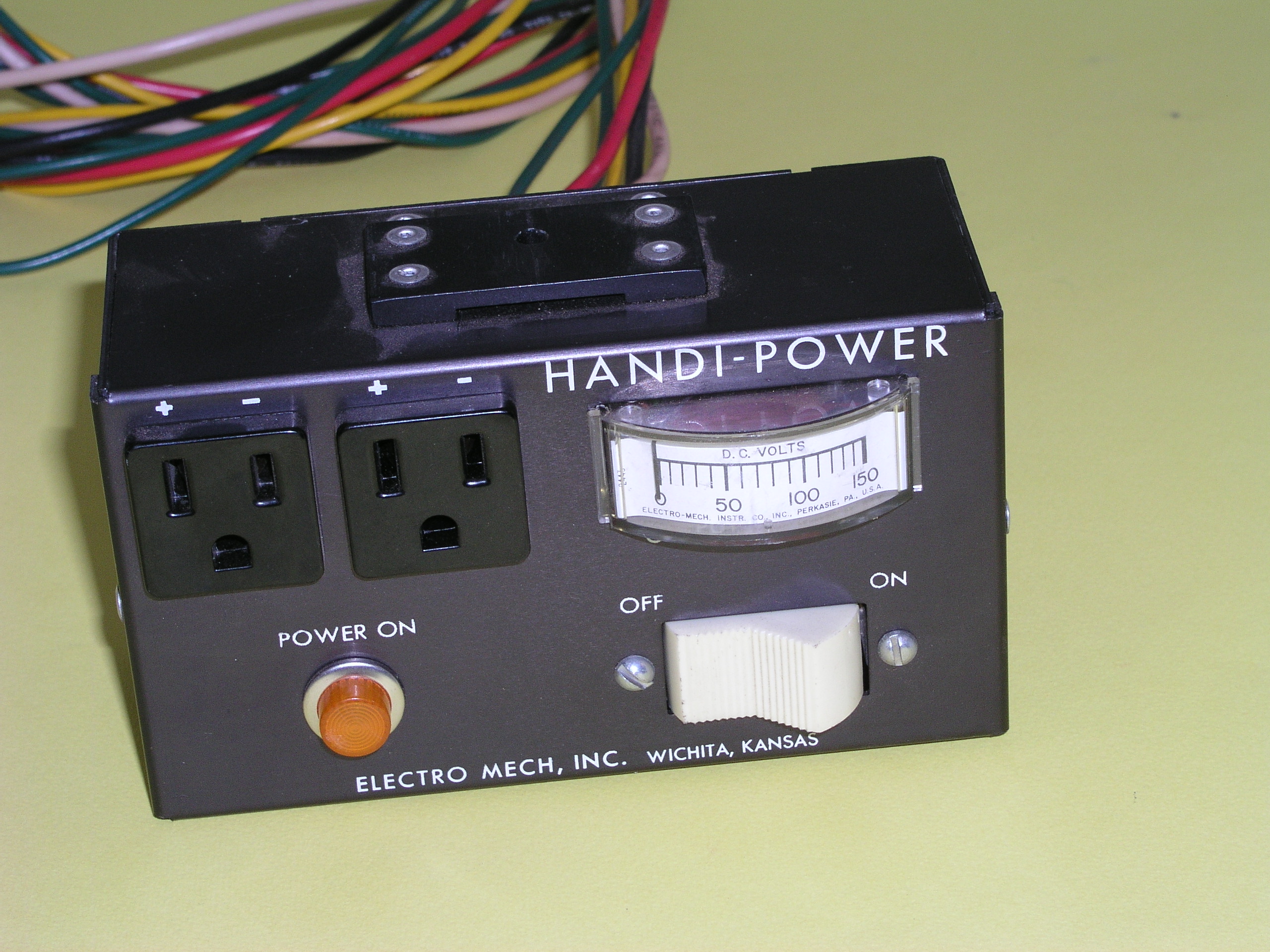
no so robust. I first hired into Electro-Mech about
1975. One of our products was a device you could add
to your alternator-fitted automobile to convert it
to a 100V dc power source to run lights and universal
appliances 'in the field'.
Worked okay most of the time but two many installations
on Chrysler products were popping alternator diodes
as a result of this installation. Had to do a messy
recall. 30 years later, after inheriting a house from
my father, I found one of these critters new in the box
out in his shop. It never got installed.
I suspect you could make this thing work
on any modern alternator. The diodes have "come
along way baby!"
| Quote: | I assumed that that "other failure mode" would be a shorted rectifier diode
(drawing current from battery). Not sure of the likelihood of such a failure.
In my experience diodes fail open (and zeners fail shorted). |
Actually, both devices are most likely to fail
shorted due to thermal destruction of the PN
barrier.
| Quote: | I really don't like a contactor because of weight and the current it draws.
The 80A relay has a 85 ohm coil resistance. and the contactor I have 15 ohms.
2 W vs 12 W. |
The WR/Stancore contactor warms up pretty
good and will stabilize at some more
friendly current.
http://www.aeroelectric.com/Pictures/Contactors/Battery_Contactor_Temps_1.jpg
http://www.aeroelectric.com/Pictures/Contactors/Battery_Contactor_Temps_2.jpg
It will stabilize at about 0.6A at 14V or 8.5W
Does your load analysis show that 'saving' a couple
of watts is useful? But the greatest savings
are secured by not having the contactor in the
first place.
| Quote: | I should mention I'm putting a Mazda 13B (Renesis) in an RV-4. So in a battery-only
(no alternator) situation, it's important to be able to shed all loads that are not
required to keep the engine running and I'm designing to electrical system accordingly.
The manufacturer (RWS) of the engine controller recommends engine-essential item be
powered directly from battery (via one switch/breaker). However, having dissected a
failed (open) W31- breaker/switch, I'll double that with a pull-breaker, |
Why any breaker at all? Yeah, I worked on the team
that wrestled with that same failure in nearly
the entire fleet of Bonanzas and Barons.
| Quote: | and have changed from switch/breakers to a fuse block.and switches for pumps,
injectors, coils, etc. |
Yup, they ALL want you to tie right to the battery.
Suggest you consider a dual feed Engine Bus as shown
in Z101.
Bob . . .
| | - The Matronics AeroElectric-List Email Forum - | | | Use the List Feature Navigator to browse the many List utilities available such as the Email Subscriptions page, Archive Search & Download, 7-Day Browse, Chat, FAQ, Photoshare, and much more:
http://www.matronics.com/Navigator?AeroElectric-List |
|
| Description: |
|
| Filesize: |
1.15 MB |
| Viewed: |
4083 Time(s) |
|
|
|
| Back to top |
|
|
finn.lassen(at)verizon.ne
Guest
|
| Posted: Wed Apr 22, 2020 2:23 pm Post subject: OV B-lead Relay |
|
|
On 4/22/2020 1:54 PM, Robert L. Nuckolls, III wrote:
| Quote: | | �Why any breaker at all? |
Indeed, with just a fusible link between battery and engine fuse block, why a switch-breaker?
The only answer I can come up with: convenience.
Powered by the engine bus are:
Engine controller A
Engine Controller B (yes, redundant controllers)
Primary fuel pump
Backup fuel pump
Primary fuel injectors
Secondary fuel injectors (fuel injection is staged, at certain MAP the second set of injectors are used too)
Leading ignition coils
Trailing ignition coils (13B has two spark plugs per rotor)
Engine monitor (strictly speaking not needed for engine to keep running)
O2 sensor (strictly speaking not needed for engine to keep running)
Left to right tank transfer pump (strictly speaking not needed for engine to keep running)
Starter relay (strictly speaking not needed for engine to keep running)
Put the last four items on the engine bus "because they are engine related".
After normal flight I will have to shut off 9 to10 switches rather than just one to ensure that engine bus does not drain battery.
Separate switches for A & B controllers are not mentioned by the manufacturer. He recommends just a switch/breaker directly to battery feeding controllers and monitor. But for reason mentioned earlier, I now prefer fuses and like the ability to disconnect a misbehaving controller. (There is an A/B switch, so really would be for the rare situation where voltage regulator in one controller draws high current without blowing its fuse.) Could have one switch, but then I would want inline fuses after the switch.
Regarding diodes feeding engine bus, from the EC3 manual:
"Also note that the use of main battery power contactors and power distribution devices incorporating isolation diodes for backup battery connections are not recommended for alternative engine installations."
I can only guess the reason is that a diode will prevent the battery to act as a very effective noise filter.
Thank you Bob for all you do and your advice.
Finn
| | - The Matronics AeroElectric-List Email Forum - | | | Use the List Feature Navigator to browse the many List utilities available such as the Email Subscriptions page, Archive Search & Download, 7-Day Browse, Chat, FAQ, Photoshare, and much more:
http://www.matronics.com/Navigator?AeroElectric-List |
|
|
|
| Back to top |
|
|
nuckolls.bob(at)aeroelect
Guest
|
| Posted: Wed Apr 22, 2020 4:23 pm Post subject: OV B-lead Relay |
|
|
At 05:17 PM 4/22/2020, you wrote:
| Quote: | On 4/22/2020 1:54 PM, Robert L. Nuckolls, III wrote:
| Quote: | | �Why any breaker at all? |
Indeed, with just a fusible link between battery and engine fuse block, why a switch-breaker?
The only answer I can come up with: convenience. |
The Engine Bus is part of your power distribution
system. As a member of the FAT-wire family, no
disconnects for the bus are called for . . . see
Engine Bus in Z1010
| Quote: | Powered by the engine bus are:
Engine controller A
Engine Controller B (yes, redundant controllers)
Primary fuel pump
Backup fuel pump
Primary fuel injectors
Secondary fuel injectors (fuel injection is staged, at certain MAP the second set of injectors are used too)
Leading ignition coils
Trailing ignition coils (13B has two spark plugs per rotor)
Engine monitor (strictly speaking not needed for engine to keep running)
O2 sensor (strictly speaking not needed for engine to keep running)
Left to right tank transfer pump (strictly speaking not needed for engine to keep running)
Starter relay (strictly speaking not needed for engine to keep running)
Put the last four items on the engine bus "because they are engine related".
After normal flight I will have to shut off 9 to10 switches rather than
just one to ensure that engine bus does not drain battery. |
10 switches? This sounds like a recipe for mis-selection
in times of stressful ops. How will your check-list read
for "In case of engine malfunction". If there is no
check list included in the engine documentation, then
CREATE ONE. You don't want to succumb to switch-flipitis
at 8,000 feet.
| Quote: | Separate switches for A & B controllers are not mentioned by the manufacturer.
He recommends just a switch/breaker directly to battery feeding controllers
and monitor. |
but he is not a system integrator
| Quote: | But for reason mentioned earlier, I now prefer fuses and like the
ability to disconnect a misbehaving controller. (There is an A/B switch,
so really would be for the rare situation where voltage regulator in one
controller draws high current without blowing its fuse.) |
How about a two pole switch. One pole for each
controller. Each protected by a fuse AT THE BUS?
| Quote: | Could have one switch, but then I would want inline fuses after the switch.
Regarding diodes feeding engine bus, from the EC3 manual:
"Also note that the use of main battery power contactors and
power distribution devices incorporating isolation diodes for
backup battery connections are not recommended for alternative
engine installations."
I can only guess the reason is that a diode will prevent the battery to act as a very effective noise filter. |
Don't GUESS . . . KNOW. Call the dude up and
get an explanation. BTW, batteries are not
'noise filters' at any level.
| Quote: | | Thank you Bob for all you do and your advice. |
You're most welcome my friend. That's what
we do here . . .
Is there a .pdf installation manual for this system
that I could see?
Bob . . .
| | - The Matronics AeroElectric-List Email Forum - | | | Use the List Feature Navigator to browse the many List utilities available such as the Email Subscriptions page, Archive Search & Download, 7-Day Browse, Chat, FAQ, Photoshare, and much more:
http://www.matronics.com/Navigator?AeroElectric-List |
|
|
|
| Back to top |
|
|
finn.lassen(at)verizon.ne
Guest
|
| Posted: Wed Apr 22, 2020 5:20 pm Post subject: OV B-lead Relay |
|
|
On 4/22/2020 8:19 PM, Robert L. Nuckolls, III wrote:
| Quote: | �10 switches? This sounds like a recipe for mis-selection
�in times of stressful ops. How will your check-list read
�for "In case of engine malfunction". |
Yes, one definitely needs to be familiar with how the system functions.
I've been flying my RV-3B with basically the same system for 100s of hours.
I am developing checklists, but will be no substitute for knowing how the system works when it comes to troubleshooting.
Example of run-up procedure (to test that backup pump, both controllers, all ignition coils and injectors work):
Turn on backup fuel pump, fuel pressure should rise a bit, turn back off.
RPM to 3,600, adjust mixture as needed.
Turn off primary injectors, note RPM drop, turn back on.
Turn off secondary injectors, note RPM drop, turn back on.
Select controller B.
Disable leading coils ( (On)-Off-(On) switch), note RPM drop.
Disable trailing coils (same (On)-Off-(On) switch), note RPM drop.
Select controller A.
RPM to idle.
(The two switches powering the leading and trailing coil sets are purely for troubleshooting and to turn off power to the coils. It could be just one switch, but then would want in-line fuses after the switch.)
I can understand how so many switches can appear confusing, but in practice it becomes second nature.
"How about a two pole switch. One pole for each
� controller. Each protected by a fuse AT THE BUS?"
Nope, controllers are designed to normally both be powered on. For example, there is an option to copy tuning parameters from A to B (should not be done in the air).
" Is there a .pdf installation manual for this system
� that I could see?"
Emailed you the manual. Doesn't really belong on this list, even though everything is now open source after Tracy retired.
Finn
| | - The Matronics AeroElectric-List Email Forum - | | | Use the List Feature Navigator to browse the many List utilities available such as the Email Subscriptions page, Archive Search & Download, 7-Day Browse, Chat, FAQ, Photoshare, and much more:
http://www.matronics.com/Navigator?AeroElectric-List |
|
|
|
| Back to top |
|
|
ceengland7(at)gmail.com
Guest
|
| Posted: Thu Apr 23, 2020 4:20 pm Post subject: OV B-lead Relay |
|
|
On 4/21/2020 8:59 PM, Robert L. Nuckolls, III wrote:
| Quote: | | Quote: | | Quote: | | My admittedly sometimes faulty memory of the whole 'load dump' situation two decades ago was that guys were flipping their alt switches/breakers (which controlled the B lead contactor) while the alt was under load, and killing the alt. IIRC, after multiple incidents like that, the OV module/contactor circuit became a lot harder to find in the AEC docs. |
|
Yeah, your memory is correct. The Z24 pot boiled
over when I think only one individual experienced
alternator failure after cycling it. We don't know
how fast the engine was running or what the alternator
loads were . . . you never get that quality of data
from someone pointing a figure at you hollering, "you
alternator killer!"
I think Paul M was a well entrenched advisor to
that faction of RV fans and he was rather antagonistic
to anything 'crowbar'.
| Quote: | | My solution is the He Haw Solution: 'If it hurts when you do that, DON'T DO THAT!' |
Exactly. If the alternator is brought off and
on line at engine idle (standard ops) then
there is no risk.
| Quote: | | Here's my take: If I operate the IR alternator just like it's operated in the car, I'll never have a load dump event. If I use an OV module that is relatively immune to 'false positives', along with a relatively robust B lead contactor, the only penalty I see is carrying a few ounces of extra weight for the contactor. The contactor will never operate unless the regulator has failed (in an OV mode), in which case the 'load dump' issue is already moot. |
That was the spirit and intent of the design
but I failed to include a note precluding random
operations at high rpm. In all fairness, any
alternator should be able to respond safely
to on/off commands under any speed and load
conditions.
| Quote: | | This lets me use an off the shelf, *very inexpensive*, available at any auto supply, alternator. It won't be as reliable as a B&C, but based on anecdotal evidence from RV-x owners, a *lot* more reliable than a Plane Power. And I'll have about $500 left over to buy fuel. (Replacement alts, if ever needed, will be free.) If I do have to replace the alt while away from home, no mod to the alt is needed, and replacement can happen on the ramp with only a couple of wrenches. |
Is PlanePower having issues? I think they
were bought out by a company that shall
remain nameless. Has their craftsmanship
suffered?
| Quote: | | I have had several different 'lives' as an electronics tech, from home electronics to pro sound, to industrial gear. Even though I'd consider myself to be well above average in qualifications, I trust an 'as-built' alternator to be more reliable than one that I've modded. |
YEeaahh . . . with reservations. The recent
Kitplanes article we've discussed here is
a rather benign operation . . . with profound
benefit.
| Quote: | | My opinion is that if any update is made, it would be to redesign the OV module to reduce the risk of 'false positive' nuisance trips, and retain the B lead relay. Perhaps do a little testing on whether a single contact automotive cube relay can reliably open the B lead, *once*, as Bob Noffs mentioned, and treat the relay as if it's a fusible link. |
If we combined the crowbar feature with
the 200A 'cube' relay, the ov sense could
be a microcontroller that waits until the
relay contacts are sensed to be open before
triggering the FET. That would reduce abuse
to the relay to insignificance for both
an OV shutdown -AND- the normal on/off commands
at ANY rpm.
To be sure, MOST modern alternators including
rebuilds should be able to stand off the load
dump spike.
| Quote: | | Realistically, if the OV module fires at ~16V, how much energy is really there? How much delay will there be from hitting the voltage threshold to the contacts opening? If we used a 100A cube relay (which *should*, by definition, be able to actively control a 100A load), will it really be stressed by 60-70 amps at ~20V? Or will the voltage (and energy) be much higher by the time the contacts actually start to open? I realize that voltage will spike upward as the contacts separate, but will it be bad enough in a 'one shot' environment to weld the contacts? |
Yeah, an ov trip condition is asserted when
bus voltage rises above 16v for say 500 mS.
By this time, the energy 'spring' in the
failed alternator is really wound up pretty
good. I've observed field voltages on the
order of 1 to 2 volts for alternators carrying
a normal running load at cruise rpm. So
if you suddenly increase that voltage to 15v,
the 'spring' starts winding rapidly while held
at bay by the battery+system loads.
This is the special condition that might be
handled nicely with a fat-FET and relay.
. . . I'd want to do some studies on the
alternator test stand before running very far down
that rabbit hole.
But FOR SURE . . . a fat-FET and diode would
be a piece of cake because there's no timing
to worry about and the b-lead never rises very
far given that it's loaded down by the ship's
battery. Best yet, no concerns for keeping your
contacts out of the fire.
For an AUX alternator in the 20-30A class,
the diode/fet crowbar need not be very
beefy. Maybe not so attractive for MAIN
alternators in the 60A+ class. Voltage
drop across the diode becomes an energy
management issue.
There was a time that Cessna was using
some fat diodes in the alternator b-leads
to orchestrate an alternator failure
sensor some guy at Cessna dreamed up . . .
not me!
Here are some excerpts from a kit I wrote to
put a 100A alternator on a USAF U17. That
diode dropped about 0.9V at 100A for a
dissipation the order of 90W. Needless
to say, the heatsink was impressive. I
seem to recall we did a similar thing
on the C337. Had to dig pretty deep into
the archives for those images. Wrote that
kit in 1968!
A Schottky b-lead diode for a 30A alternator
would be much more manageable.
Bob . . . |
Sorry for the tardy reply; been a bit 'distracted'.
RE: Plane Power alts. No personal experience, but the RV guys are a fairly large sample (in a/c terms). If you go to the VAF forum and search 'plane power', you'll find dozens of instances where the brand has failed at low to very low hours. I think I've only seen one or two B&C failures mentioned. Now this could be because it is the one Van's offers when you buy an alt from them, so the population is higher. But the guys who buy again seem to often report additional failures, while those who convert to B&C don't. The guys who've done autopsies aren't just reporting electronic failures; there are connector issues, failed internal stator and/or field leads, etc etc.
RE: crowbar redesign for IR alts. You wrote:
"If we combined the crowbar feature with
the 200A 'cube' relay, the ov sense could
be a microcontroller that waits until the
relay contacts are sensed to be open before
triggering the FET. That would reduce abuse
to the relay to insignificance for both
an OV shutdown -AND- the normal on/off commands
at ANY rpm."
Is this the correct order for protecting the relay contacts? I would have thought that the FET should sit between the B terminal and relay, and fire *1st*, so that there isn't a high energy arc at the relay contacts. I'd expect the FET to be much faster than the relay, if the protection circuit could fire the LED at the same instant that it crowbars the CB feeding the relay (even without a microcontroller to do the timing). Did I misunderstand the goal, or circuit arrangement?
Charlie
 Virus-free. www.avast.com [url=#DAB4FAD8-2DD7-40BB-A1B8-4E2AA1F9FDF2] [/url] Virus-free. www.avast.com [url=#DAB4FAD8-2DD7-40BB-A1B8-4E2AA1F9FDF2] [/url]
| | - The Matronics AeroElectric-List Email Forum - | | | Use the List Feature Navigator to browse the many List utilities available such as the Email Subscriptions page, Archive Search & Download, 7-Day Browse, Chat, FAQ, Photoshare, and much more:
http://www.matronics.com/Navigator?AeroElectric-List |
|
|
|
| Back to top |
|
|
nuckolls.bob(at)aeroelect
Guest
|
| Posted: Thu Apr 23, 2020 5:00 pm Post subject: OV B-lead Relay |
|
|
| Quote: | | RE: Plane Power alts. No personal experience, but the RV guys are a fairly large sample (in a/c terms). If you go to the VAF forum and search 'plane power', you'll find dozens of instances where the brand has failed at low to very low hours. I think I've only seen one or two B&C failures mentioned. Now this could be because it is the one Van's offers when you buy an alt from them, so the population is higher. But the guys who buy again seem to often report additional failures, while those who convert to B&C don't. The guys who've done autopsies aren't just reporting electronic failures; there are connector issues, failed internal stator and/or field leads, etc etc. |
Hmmmm . . . interesting. I had occasion to
do failure analysis on another Hartzell
alternator supplied to a UAV project.
Again, no 'electronic' failure but a
failure in craftsmanship.
| Quote: | RE: crowbar redesign for IR alts. You wrote:
"If we combined the crowbar feature with
the 200A 'cube' relay, the ov sense could
be a microcontroller that waits until the
relay contacts are sensed to be open before
triggering the FET. That would reduce abuse
to the relay to insignificance for both
an OV shutdown -AND- the normal on/off commands
at ANY rpm."
Is this the correct order for protecting the relay contacts? I would have thought that the FET should sit between the B terminal and relay, and fire *1st*, so that there isn't a high energy arc at the relay contacts. I'd expect the FET to be much faster than the relay, if the protection circuit could fire the LED at the same instant that it crowbars the CB feeding the relay (even without a microcontroller to do the timing). Did I misunderstand the goal, or circuit arrangement? |
You need to wait until the contacts
were first break so that the FET wasn't trying
to crowbar BOTH the alternator and battery. This
is what makes the FAT diode isolator electrically
more attractive. OV sense and reaction becomes
a lot easier.
Bob . . .
| | - The Matronics AeroElectric-List Email Forum - | | | Use the List Feature Navigator to browse the many List utilities available such as the Email Subscriptions page, Archive Search & Download, 7-Day Browse, Chat, FAQ, Photoshare, and much more:
http://www.matronics.com/Navigator?AeroElectric-List |
|
|
|
| Back to top |
|
|
ceengland7(at)gmail.com
Guest
|
| Posted: Thu Apr 23, 2020 5:41 pm Post subject: OV B-lead Relay |
|
|
On 4/23/2020 7:55 PM, Robert L. Nuckolls, III wrote:
| Quote: | | Quote: | | RE: Plane Power alts. No personal experience, but the RV guys are a fairly large sample (in a/c terms). If you go to the VAF forum and search 'plane power', you'll find dozens of instances where the brand has failed at low to very low hours. I think I've only seen one or two B&C failures mentioned. Now this could be because it is the one Van's offers when you buy an alt from them, so the population is higher. But the guys who buy again seem to often report additional failures, while those who convert to B&C don't. The guys who've done autopsies aren't just reporting electronic failures; there are connector issues, failed internal stator and/or field leads, etc etc. |
Hmmmm . . . interesting. I had occasion to
do failure analysis on another Hartzell
alternator supplied to a UAV project.
Again, no 'electronic' failure but a
failure in craftsmanship.
| Quote: | RE: crowbar redesign for IR alts. You wrote:
"If we combined the crowbar feature with
the 200A 'cube' relay, the ov sense could
be a microcontroller that waits until the
relay contacts are sensed to be open before
triggering the FET. That would reduce abuse
to the relay to insignificance for both
an OV shutdown -AND- the normal on/off commands
at ANY rpm."
Is this the correct order for protecting the relay contacts? I would have thought that the FET should sit between the B terminal and relay, and fire *1st*, so that there isn't a high energy arc at the relay contacts. I'd expect the FET to be much faster than the relay, if the protection circuit could fire the LED at the same instant that it crowbars the CB feeding the relay (even without a microcontroller to do the timing). Did I misunderstand the goal, or circuit arrangement? |
You need to wait until the contacts
were first break so that the FET wasn't trying
to crowbar BOTH the alternator and battery. This
is what makes the FAT diode isolator electrically
more attractive. OV sense and reaction becomes
a lot easier.
Bob . . . |
Ah...yes. Forgot that the battery would try to drive the short.
Thanks for clearing my head. 
| | - The Matronics AeroElectric-List Email Forum - | | | Use the List Feature Navigator to browse the many List utilities available such as the Email Subscriptions page, Archive Search & Download, 7-Day Browse, Chat, FAQ, Photoshare, and much more:
http://www.matronics.com/Navigator?AeroElectric-List |
|
|
|
| Back to top |
|
|
|
|
You cannot post new topics in this forum
You cannot reply to topics in this forum
You cannot edit your posts in this forum
You cannot delete your posts in this forum
You cannot vote in polls in this forum
You cannot attach files in this forum
You can download files in this forum
|
Powered by phpBB © 2001, 2005 phpBB Group
|

