 |
Matronics Email Lists
Web Forum Interface to the Matronics Email Lists
|
| View previous topic :: View next topic |
| Author |
Message |
ceengland7(at)gmail.com
Guest
|
 Posted: Tue Mar 31, 2020 5:58 pm Post subject: Z11 "Generic Electrical system" with Dual Electron Posted: Tue Mar 31, 2020 5:58 pm Post subject: Z11 "Generic Electrical system" with Dual Electron |
 |
|
On 3/31/2020 6:27 PM, bcone1381 wrote:
| Quote: |
Greetings;
I'm applying the wisdom gleaned from The Aeroelectric Connection and request feedback.
The Aircraft:
-A basic VFR Bearhawk Patrol, which is a Aviat Husky/Super cub type of aircraft
-Dual Surefly Electronic Ignition modules to replace Magnetos.
Electrical system Goal:
-Simple reliability,
-Power Dual Electronic Ignition, plus simple stuff like a comm radio, transponder, a fuel pump, LED NAV lights and a few other things.
The Z11 digram titled ââ¬ÅGeneric Light Aircraft Electrical Systemââ¬Â is my favorite.
But the Dual Electronic Ignition needs are special. I called Surefly and they agreed that prudence demands I install a dedicated battery for each ignition module.
Further guidance from the Ignition Supplier
-Use a hefty diode to the Aux Batt to reliably protect it from back feeding
-Monitor the Voltage to the Aux Batt.
-Size of Aux Battery can be small, just so its duration exceeds the fuel duration. 8 amp hour?
Some here might be interested in electrical needs of a single ignition module.
-Required Voltage = 8-30V
-Amp draw = 0.7A +/- 0.2A at 2700 RPM
-Permanently connect Power to the + Batt terminal OR the Master Solenoid battery + input.
-Use 14AWG and a 10A fuse or CB.
-When the Ignition is placed in Standby mode (turned off) by grounding the P-lead, it draws less than 1ma.
So, I'm proposing a Z11 system with one ignition wired directly to a normal size Main Battery, and the second ignition wired directly to a small single purpose Aux Battery.
Although Bobââ¬â¢s Book has a Dual Batt diagram, In the spirit of simplicity I didn't use a solenoid for the Aux Battery, I protect the aux battery with a diode, and I will monitor the voltage of the Aux battery.
What are your thoughts?
--------
Brooks Cone
Bearhawk Patrol Kit Build
Read this topic online here:
http://forums.matronics.com/viewtopic.php?p=495508#495508
Attachments:
http://forums.matronics.com//files/img_0518_119.jpg
http://forums.matronics.com//files/screen_shot_2020_03_31_at_41808_pm_464.png
Hi Brooks, welcome aboard.
|
looking at the 1st drawing:
B lead protection should be at the other end (at the solenoid terminal)
to protect the wire from the battery. The B lead should be sized large
enough that the alt can't hurt it.
As drawn, the ESS bus is always hot (directly tied to the main battery).
As drawn, the aux battery and L ign are always hot (tied to battery
through the diode).
As drawn, the R ign is always hot (directly tied to the main battery).
I don't fly enough to trust that the ignitions wouldn't run the
batteries down while the plane sits idle. Might not be a factor for you.
I'd also want positive control over the ignitions; I suppose that
pullable CBs would accomplish that.
Hope the above is helpful.
Congrats on the Patrol; Bearhawk does nice airplanes.
Charlie
--
This email has been checked for viruses by Avast antivirus software.
https://www.avast.com/antivirus
| | - The Matronics AeroElectric-List Email Forum - | | | Use the List Feature Navigator to browse the many List utilities available such as the Email Subscriptions page, Archive Search & Download, 7-Day Browse, Chat, FAQ, Photoshare, and much more:
http://www.matronics.com/Navigator?AeroElectric-List |
|
|
|
| Back to top |
|
 |
bcone1381
Joined: 25 Apr 2017
Posts: 42
Location: Southeast Michigan
|
| Posted: Wed Apr 01, 2020 5:32 am Post subject: Re: Z11 |
|
|
| ceengland7(at)gmail.com wrote: | On 3/31/2020 6:27 PM, bcone1381 wrote:
| Quote: |
Greetings;
I'm applying the wisdom gleaned from The Aeroelectric Connection and request feedback.
The Aircraft:
-A basic VFR Bearhawk Patrol, which is a Aviat Husky/Super cub type of aircraft
-Dual Surefly Electronic Ignition modules to replace Magnetos.
Electrical system Goal:
-Simple reliability,
-Power Dual Electronic Ignition, plus simple stuff like a comm radio, transponder, a fuel pump, LED NAV lights and a few other things.
The Z11 digram titled ââ¬ÅGeneric Light Aircraft Electrical Systemââ¬Â is my favorite.
But the Dual Electronic Ignition needs are special. I called Surefly and they agreed that prudence demands I install a dedicated battery for each ignition module.
Further guidance from the Ignition Supplier
-Use a hefty diode to the Aux Batt to reliably protect it from back feeding
-Monitor the Voltage to the Aux Batt.
-Size of Aux Battery can be small, just so its duration exceeds the fuel duration. 8 amp hour?
Some here might be interested in electrical needs of a single ignition module.
-Required Voltage = 8-30V
-Amp draw = 0.7A +/- 0.2A at 2700 RPM
-Permanently connect Power to the + Batt terminal OR the Master Solenoid battery + input.
-Use 14AWG and a 10A fuse or CB.
-When the Ignition is placed in Standby mode (turned off) by grounding the P-lead, it draws less than 1ma.
So, I'm proposing a Z11 system with one ignition wired directly to a normal size Main Battery, and the second ignition wired directly to a small single purpose Aux Battery.
Although Bobââ¬â¢s Book has a Dual Batt diagram, In the spirit of simplicity I didn't use a solenoid for the Aux Battery, I protect the aux battery with a diode, and I will monitor the voltage of the Aux battery.
What are your thoughts?
--------
Brooks Cone
Bearhawk Patrol Kit Build
Read this topic online here:
http://forums.matronics.com/viewtopic.php?p=495508#495508
Attachments:
http://forums.matronics.com//files/img_0518_119.jpg
http://forums.matronics.com//files/screen_shot_2020_03_31_at_41808_pm_464.png
Hi Brooks, welcome aboard.
|
looking at the 1st drawing:
B lead protection should be at the other end (at the solenoid terminal)
to protect the wire from the battery. The B lead should be sized large
enough that the alt can't hurt it.
As drawn, the ESS bus is always hot (directly tied to the main battery).
As drawn, the aux battery and L ign are always hot (tied to battery
through the diode).
As drawn, the R ign is always hot (directly tied to the main battery).
I don't fly enough to trust that the ignitions wouldn't run the
batteries down while the plane sits idle. Might not be a factor for you.
I'd also want positive control over the ignitions; I suppose that
pullable CBs would accomplish that.
Hope the above is helpful.
Congrats on the Patrol; Bearhawk does nice airplanes.
Charlie
--
This email has been checked for viruses by Avast antivirus software.
https://www.avast.com/antivirus |
__________
Thanks Charlie;
B lead protection....Got it. I moved the current limiter to the solenoid end.
Essential Bus always hot...My error on the not installing a switch from the main battery to the Essential Bus. The Essential bus will draw less than 5A so I chose a switch over a solenoid.
The Ignitions are powered all the time. They are controlled by grounding the P-lead. When "off" (in standby mode) they will draw about 1 miliamp. You dont control them with a traditional power switch. They will draw down a battery over time so a battery maintainer is prudent.
| | - The Matronics AeroElectric-List Email Forum - | | | Use the List Feature Navigator to browse the many List utilities available such as the Email Subscriptions page, Archive Search & Download, 7-Day Browse, Chat, FAQ, Photoshare, and much more:
http://www.matronics.com/Navigator?AeroElectric-List |
|
_________________
Brooks Cone
Bearhawk Patrol Kit Build |
|
| Back to top |
|
|
ceengland7(at)gmail.com
Guest
|
| Posted: Wed Apr 01, 2020 9:58 am Post subject: Z11 "Generic Electrical system" with Dual Electron |
|
|
On 4/1/2020 11:20 AM, bcone1381 wrote:
| Quote: |
> Your task then is to PROVIDE failure-tolerant
> power sources to critical equipment such that
> no single failure puts the airframe (and by
> extension it's occupants) at risk.
>
> .....The premise behind this idea is that airplanes
> have a family of devices presenting various levels
> of criticality for comfortable termination
> of flight. So you have dual electronic
> ignition? Fine . . . are you comfortable
> launching into the blue not having offered
> the rest of your electro-whizzies the same
> courtesies as your ignition systems? If not,
> the does it not stand to reason that if
> the rest of your 'critical' systems are
> happy, so too will be your ignition systems?
>
> The optimal answer is 'fix the architecture'
> and leave the batteries on the dealer's shelves.
The Ignition is the critical item. I am comfortable loosing power to all the electronics other than the ignition, therefore the electrical system architecture is being designed to accommodate it.
> Have you considered the fledgling architecture posted
> here on the list a few weeks back . . . See
>
> https://tinyurl.com/qnzenca
>
Kind of......I considered the diagram but not the architecture. Dual alternators, brownout bus, it seemed complex for my application. My perception is electrical demands for EFI are large compared with my choice of ignition at 1.4A total. Since both ignitions tied to a single battery was not failure tolerant , the SureFly small second battery (12V 8Ahr is $50) seemed simple.
> Let's do our homework and see if we can
> figure out how to make your project fly
> comfortably on one, judiciously maintained
> battery . . . just has hundreds of thousands
> of airplanes have flown for over a century.
>
So lets reconsider that as archetecure and see what we come up with.
I have integrated the Architecture into my diagram, and removed the Aux Battery. The load on the Engine bus will be less than 5A so I will use a switch instead of a solenoid. I removed the Battery Bus to avoid a human error that might deplete the battery out in the bush.
If the power supply from the ALT side of the master solenoid fails, the engine dies until the switch is flipped by reliable human action. Not ideal. A diode to replace the switch eliminates human failure.
The next step I see is to remove the engine bus, bolt both power wires to the Battery side of the master solenoid. Now I am chasing my tail back to where I was. But lets say I did that. If the Solenoid fails open, then the engine is battery powered while the rest of the ship is powered by the alternator.
I think you already discussed months ago, but it looks to me like the Engine Bus duplicates the Essential bus.
How am I doing?
--------
Brooks Cone
Bearhawk Patrol Kit Build
I certainly lack Bob's knowledge and experience, but for a minimalist
|
system, I like it. You could lose the switch between the main bus diode
and the Ess bus; the Ess bus would normally be fed from the main bus and
have 'required' avionics. If the alt fails, you'd close the switch
that's direct from the bat and open the master.
To avoid the issue of the master taking out both ignitions, I'd operate
with both the mstr and the engine bus direct feed switch closed (no harm
in feeding the eng bus from both ends at the same time). I'd keep the
Eng bus diode because I like redundant paths to critical stuff.
To address the backup alternator issue that Bob raised: My installation
uses auto style injection which requires a high pressure fuel pump (high
current demand) so I chose to use two full size alts. But if you're
running a carb and your electrical demands are quite low, I can
understand not adding a 2nd alt, from both financial and weight
standpoints. In my situation, with around 12A minimum needed to keep the
engine running, battery capacity to operate to fuel exhaustion (my
personal choice) would have weighed *much* more than an additional 8 lb
alternator, and would have cost more than my off-the-shelf auto
alternator, as well. But your low-demand system likely means that a
standard PC680 style battery could run to fuel exhaustion. (Caution: do
your load analysis, backed up by actual testing, and be sure you
understand the various demand/time curves for PC680 type batteries.)
Charlie
--
This email has been checked for viruses by Avast antivirus software.
https://www.avast.com/antivirus
| | - The Matronics AeroElectric-List Email Forum - | | | Use the List Feature Navigator to browse the many List utilities available such as the Email Subscriptions page, Archive Search & Download, 7-Day Browse, Chat, FAQ, Photoshare, and much more:
http://www.matronics.com/Navigator?AeroElectric-List |
|
|
|
| Back to top |
|
|
foghorn757(at)gmail.com
Guest
|
| Posted: Wed Apr 01, 2020 10:11 am Post subject: Z11 "Generic Electrical system" with Dual Electron |
|
|
Here is the electrical diagram Iâm using for my aircraft. Dual SDS EFI, single battery and dual alternators. This architecture is Z12/13 modified and was originally drawn up by John Bright, weâve been working together to improve it (in our opinion). This is version 4 and Iâm still making minor tweaks.
Since you have dual electronic ignition I would recommend either dual batteries/single ALT or dual alternators/single battery. The SD8 that Bob mentioned a few emails back is a great idea for a VFR bush plane. Because even your VFR only Bearhawk is going to fly over inhospitable terrain from time to time.
I know, I knowâ¦using a VP-X is blasphemy. It came with the kit I purchased from a friend.
PSâ¦..the Bearhawk Patrol is probably my next aircraft build.
Jeff Parker
| Quote: | On 1Apr, 2020, at 13:39, user9253 <fransew(at)gmail.com (fransew(at)gmail.com)> wrote:
--> AeroElectric-List message posted by: "user9253" <fransew(at)gmail.com (fransew(at)gmail.com)>Why put a switch in series with the E-Bus diode?I suggest that switch be eliminated. If it is not installed, it can not fail.-I suggest that a double pole switch be used for the engine bus switch.The second half of that switch can enable the engine start circuit. Properly wired, the engine bus switch must be on in order to start the engine.--------Joe GoresRead this topic online here:http://forums.matronics.com/viewtopic.php?p=495528#495528
|
| | - The Matronics AeroElectric-List Email Forum - | | | Use the List Feature Navigator to browse the many List utilities available such as the Email Subscriptions page, Archive Search & Download, 7-Day Browse, Chat, FAQ, Photoshare, and much more:
http://www.matronics.com/Navigator?AeroElectric-List |
|
| Description: |
|

Download |
| Filename: |
SINGLE_FWD_BATT_SDS_Rev4.pdf |
| Filesize: |
485.65 KB |
| Downloaded: |
238 Time(s) |
|
|
| Back to top |
|
|
ceengland7(at)gmail.com
Guest
|
| Posted: Fri Apr 03, 2020 4:24 pm Post subject: Z11 "Generic Electrical system" with Dual Electron |
|
|
On 4/2/2020 11:08 AM, Robert L. Nuckolls, III wrote:
| Quote: | At 06:09 PM 4/1/2020, you wrote:
| Quote: | --> AeroElectric-List message posted by: "user9253" <fransew(at)gmail.com> (fransew(at)gmail.com)
Bob, In figure Z-01, Should the brownout bus fuse be increased in size from 10 amps to 30 amps?
Since that fuse is in series with other fuses, we wouldn't want a short circuit to blow two fuses.
|
Good observation . . . fuses, wire sizes and bus
loads are evolving . . .
Speaking of evolution, I'm still wrestling with the
notion of driving the crowbar ov breaker bus extension
through a ATC fuse on the fuseblock. I cannot guarantee
that every future builder would use a breaker having
I(squared)t characteristics small enough to avoid
popping that fuse.
The fusible link is still the stone simple, most
convenient way to bring power from the fuseblock
terminal to the circuit breaker. I'm researching
sources for on-purpose fusible link wire in bulk.
Much more convenient . . . than the legacy kits
we introduced 20+ years ago.
Keep up the discerning observations my friend!
Bob . . . |
Hot rod shops likely have anything we'd need for fusible links. Here's Summit's selection; everything from #10 to #18:
https://www.summitracing.com/search?SortBy=BestKeywordMatch&SortOrder=Ascending&keyword=fusible%20link%20wirees
I really like the idea of using them, especially for critical things like the feeder to the engine bus.
I've already set up an ATC fuse block with individual fuses for each injector and ignition coil, but I'm tempted to replace those fuses with fusible links. I might be wrong, but it's easy to see the links as even more reliable than ATC fuses, especially on that type of appliance that has a repetitive very sharp current spike, rather than a relatively continuous load.
Charlie
 Virus-free. www.avast.com [url=#DAB4FAD8-2DD7-40BB-A1B8-4E2AA1F9FDF2] [/url] Virus-free. www.avast.com [url=#DAB4FAD8-2DD7-40BB-A1B8-4E2AA1F9FDF2] [/url]
| | - The Matronics AeroElectric-List Email Forum - | | | Use the List Feature Navigator to browse the many List utilities available such as the Email Subscriptions page, Archive Search & Download, 7-Day Browse, Chat, FAQ, Photoshare, and much more:
http://www.matronics.com/Navigator?AeroElectric-List |
|
|
|
| Back to top |
|
|
johnbright
Joined: 14 Dec 2011
Posts: 165
Location: Newport News, VA
|
| Posted: Sat Apr 04, 2020 8:11 am Post subject: Re: Z11 |
|
|
| ceengland7(at)gmail.com wrote: | ...I've already set up an ATC fuse block with individual fuses for each injector and ignition coil, but I'm tempted to replace those fuses with fusible links. I might be wrong, but it's easy to see the links as even more reliable than ATC fuses, especially on that type of appliance that has a repetitive very sharp current spike, rather than a relatively continuous load.
Charlie |
It seems to me that ATO fuses are OK.
There is no surge aka inrush current above continuous operating current. Since there is no surge current, we don't need to look at I2T. Surge currents come from motors, filament lamps, heaters, and large capacitors for instance.
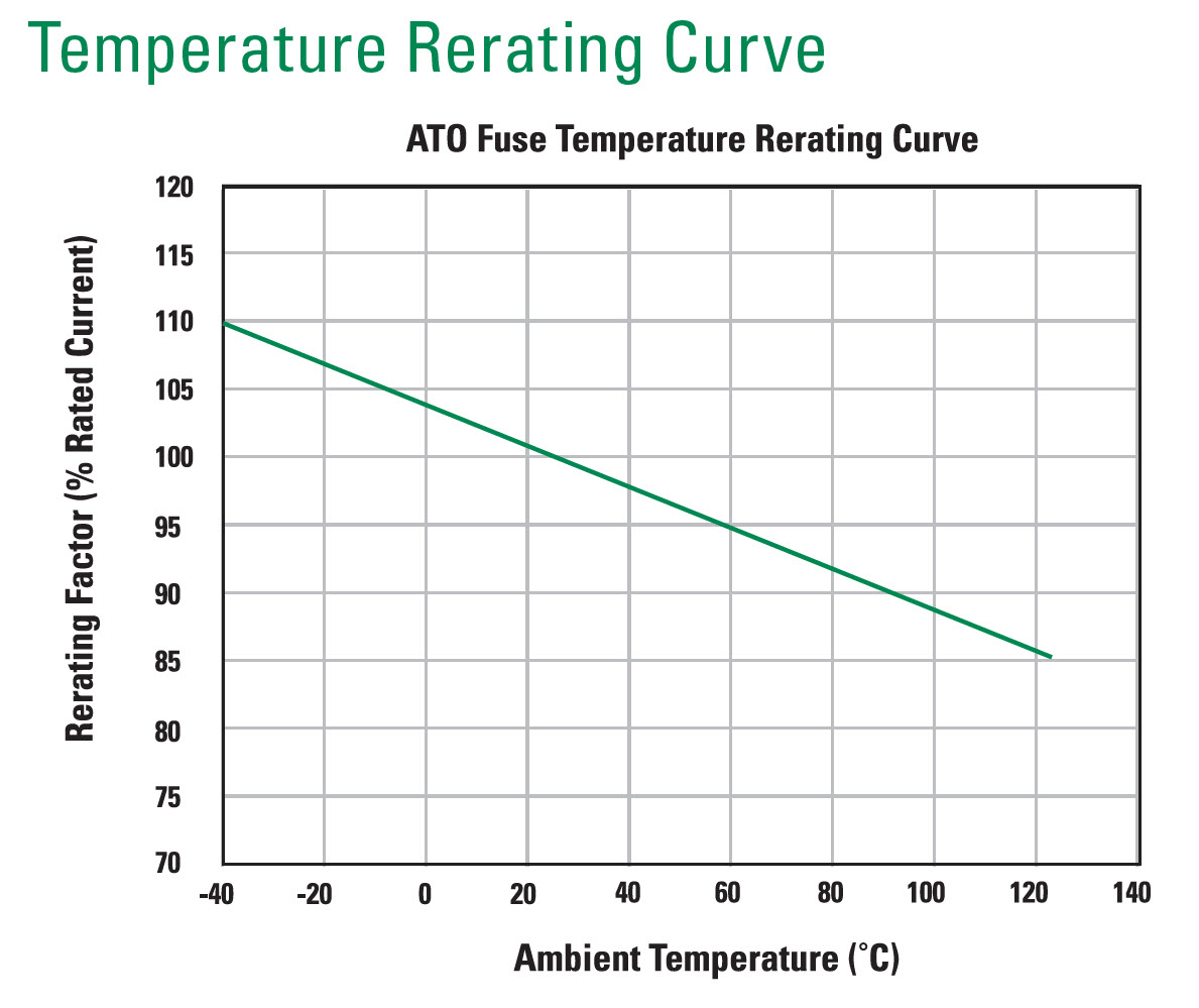
Suppose a worst case temperature of 170F on the firewall. Per Littlefuse, an ATOF fuse is derated 25% to avoid nuisance blowing and 8% for 170F. 1/(.75*.92) = 1.45. Min fuse rating = 1.45 * normal operating current.
=========================
Injectors:
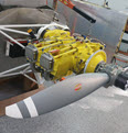
For example, SDS EM-5-F system uses 14.5 ohm "saturation" (as opposed to peak-hold which are to my knowledge used in single-point systems) injectors. Steady-state current is 1 amp per injector at 14.5 V. SDS recommends 5 A fuses, one per injector.
Repetitive: Yes, once per crank revolution I guess.
Current spike above continuous on level: No.
Current rise very sharp: Not compared to a resistive load. Inductor back EMF causes current to rise more slowly than a that of a resistive load.
Duty cycle: 85% max recommended.
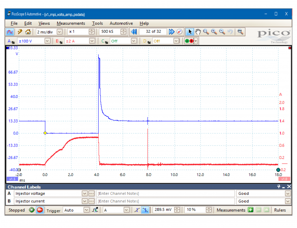
Google found a typical plot at picoauto.com, attached, of saturation injector voltage and current. The plot even seems to be for 14.5 ohm injectors given the voltage and current levels shown. Note it takes a little over 2 mS for the current to reach saturation level. BTW the dip in current rise at 1.3 mS is when the solenoid valve armature moves creating back EMF in addition to what comes from the increasing magnetic field of the stator. Another BTW, the voltage plot shows the flyback voltage created when the inductor is de-energized; this is diode clamped, at 82 V in this case, to prevent damaging the drive transistor; the higher the flyback is allowed to go, the faster the injector will close.
=========================================
Coilpacks:
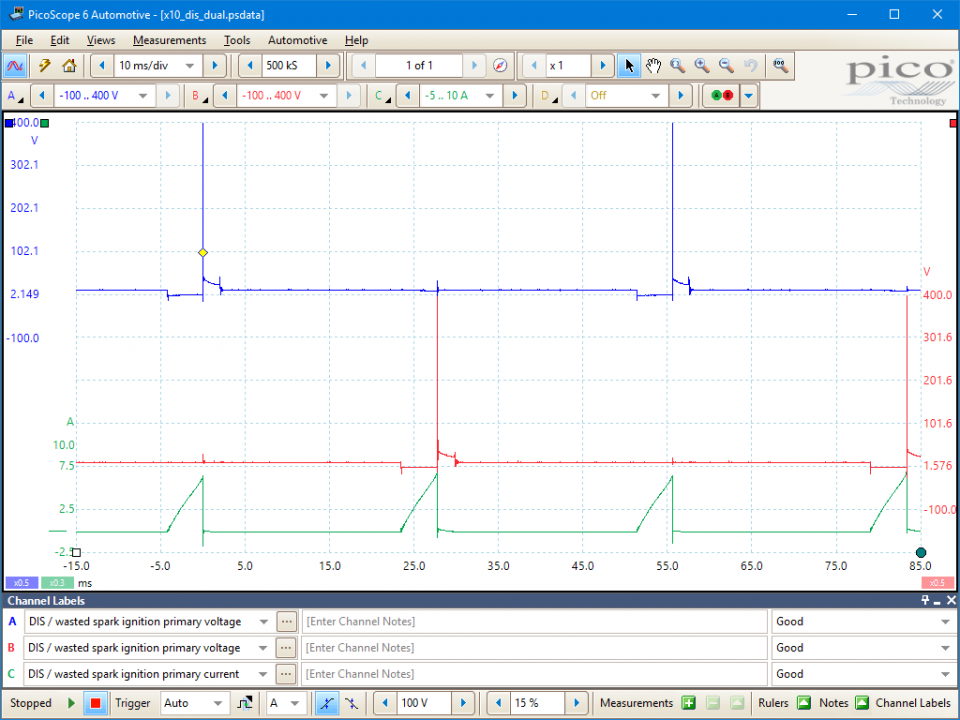
picoauto.com also has voltage and current waveforms, attached, for a typical distributorless dual driver wasted spark coilpack. Such a coilpack would be used on a four cylinder Lycoming.
This plot shows the same phenomenon of current rise slower than that of a resistive load. Saturation is not achieved, peak current is limited by dwell time rather than coil resistance. I2t of the sawtooth shown is the same as a square wave of 1/sqrt2 the height so the 6.25 A height would be 4.4A if it were a square wave of the same energy.
SDS says each of their coilpacks draw "just over 1 amp in cruise at 2,400 rpm". and they recommend a 10 A fuse for each coilpack. Using the 0.043 mS dwell time from the picoauto.com plot and assuming a four cylinder engine at 2,400 RPM I calculate an average current of 1.13 A at 2,400 rpm so this coilpack seems to be representative of the one SDS uses. In my calculations, current varies linearly with rpm.
========================================
| | - The Matronics AeroElectric-List Email Forum - | | | Use the List Feature Navigator to browse the many List utilities available such as the Email Subscriptions page, Archive Search & Download, 7-Day Browse, Chat, FAQ, Photoshare, and much more:
http://www.matronics.com/Navigator?AeroElectric-List |
|
| Description: |
|
| Filesize: |
342.12 KB |
| Viewed: |
4075 Time(s) |
|
| Description: |
|
| Filesize: |
223 KB |
| Viewed: |
4075 Time(s) |
|
| Description: |
|
| Filesize: |
123.66 KB |
| Viewed: |
4060 Time(s) |
|
_________________
John Bright, RV-6A, at FWF, O-360
Z-101 single batt dual alt SDS EM-5-F.
john_s_bright@yahoo.com, Newport News, Va
N1921R links |
|
| Back to top |
|
|
|
|
You cannot post new topics in this forum
You cannot reply to topics in this forum
You cannot edit your posts in this forum
You cannot delete your posts in this forum
You cannot vote in polls in this forum
You cannot attach files in this forum
You can download files in this forum
|
Powered by phpBB © 2001, 2005 phpBB Group
|

