 |
Matronics Email Lists
Web Forum Interface to the Matronics Email Lists
|
| View previous topic :: View next topic |
| Author |
Message |
ceengland7(at)gmail.com
Guest
|
 Posted: Sat May 26, 2018 11:56 am Post subject: Is the OVP 5 A CB supposed to trip when I switch off the al Posted: Sat May 26, 2018 11:56 am Post subject: Is the OVP 5 A CB supposed to trip when I switch off the al |
 |
|
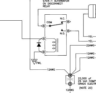
Is the diode installed correctly across the alternator disconnect relay coil?
Any chance you got the progressive master/alternator switch wired so the alt comes on line 1st, and the system comes up second?Â
On Sat, May 26, 2018 at 2:25 PM, William Daniell <wdaniell.longport(at)gmail.com (wdaniell.longport(at)gmail.com)> wrote:
| Quote: | I started my reformed electrical system today. The system is an exact Z16 with no mods. No exciting sparks or smoke and everything worked.
However with the engine running I switched off the ALT and the 5A CB in the OVP circuit immediately tripped.
I reset and turned the ALT back on and everything operated normally.
Is this supposed to happen?
thanks
Will
William Daniell
LONGPORT
+57 310 295 0744
|
| | - The Matronics AeroElectric-List Email Forum - | | | Use the List Feature Navigator to browse the many List utilities available such as the Email Subscriptions page, Archive Search & Download, 7-Day Browse, Chat, FAQ, Photoshare, and much more:
http://www.matronics.com/Navigator?AeroElectric-List |
|
|
|
| Back to top |
|
 |
wdaniell.longport(at)gmai
Guest
|
| Posted: Sat May 26, 2018 3:07 pm Post subject: Is the OVP 5 A CB supposed to trip when I switch off the al |
|
|
âSo I take it that it's not supposed to trip?
I have separate switches for the battery and alternator and they do what they are supposed to.  I don't have a diode installed. Is this critical?
ALT and the BATT are connected to the starter contactor as per Z16 (well actually Z16v shows the buss connected to the battery contractor but it looks electrically equivalent from the diagram)
So...everything is normal. I can start the engine switch on the loads - I see the ammeter reacting to the loads, the alternator is charging the battery and running all the loads. â  the System is at 12.8V.
I can switch the battery off and all remains the same.
But when I switch the ALT off the OVP trips. The amps go negative while the ALT is off. I can immediately reset the 5amp CB and switch on the ALT and everything is goes back to normal.
Could the OVP be reacting to a sudden Volt surge caused by the battery taking up the loads?
Will
On Sat, May 26, 2018, 15:00 Charlie England <ceengland7(at)gmail.com (ceengland7(at)gmail.com)> wrote:
| Quote: | Is the diode installed correctly across the alternator disconnect relay coil?
Any chance you got the progressive master/alternator switch wired so the alt comes on line 1st, and the system comes up second?Â
On Sat, May 26, 2018 at 2:25 PM, William Daniell <wdaniell.longport(at)gmail.com (wdaniell.longport(at)gmail.com)> wrote:
| Quote: | I started my reformed electrical system today. The system is an exact Z16 with no mods. No exciting sparks or smoke and everything worked.
However with the engine running I switched off the ALT and the 5A CB in the OVP circuit immediately tripped.
I reset and turned the ALT back on and everything operated normally.
Is this supposed to happen?
thanks
Will
William Daniell
LONGPORT
+57 310 295 0744
|
|
| | - The Matronics AeroElectric-List Email Forum - | | | Use the List Feature Navigator to browse the many List utilities available such as the Email Subscriptions page, Archive Search & Download, 7-Day Browse, Chat, FAQ, Photoshare, and much more:
http://www.matronics.com/Navigator?AeroElectric-List |
|
|
|
| Back to top |
|
|
user9253
Joined: 28 Mar 2008
Posts: 1913
Location: Riley TWP Michigan
|
| Posted: Sat May 26, 2018 3:33 pm Post subject: Re: Is the OVP 5 A CB supposed to trip when I switch off th |
|
|
Install that missing diode.
| | - The Matronics AeroElectric-List Email Forum - | | | Use the List Feature Navigator to browse the many List utilities available such as the Email Subscriptions page, Archive Search & Download, 7-Day Browse, Chat, FAQ, Photoshare, and much more:
http://www.matronics.com/Navigator?AeroElectric-List |
|
_________________
Joe Gores |
|
| Back to top |
|
|
ceengland7(at)gmail.com
Guest
|
| Posted: Sat May 26, 2018 3:51 pm Post subject: Is the OVP 5 A CB supposed to trip when I switch off the al |
|
|
On 5/26/2018 6:06 PM, William Daniell wrote:
| Quote: | âSo I take it that it's not supposed to trip?
I have separate switches for the battery and alternator and they do what they are supposed to.  I don't have a diode installed. Is this critical?
ALT and the BATT are connected to the starter contactor as per Z16 (well actually Z16v shows the buss connected to the battery contractor but it looks electrically equivalent from the diagram)
So...everything is normal. I can start the engine switch on the loads - I see the ammeter reacting to the loads, the alternator is charging the battery and running all the loads. â  the System is at 12.8V.
I can switch the battery off and all remains the same.
But when I switch the ALT off the OVP trips. The amps go negative while the ALT is off. I can immediately reset the 5amp CB and switch on the ALT and everything is goes back to normal.
Could the OVP be reacting to a sudden Volt surge caused by the battery taking up the loads?
Will
On Sat, May 26, 2018, 15:00 Charlie England <ceengland7(at)gmail.com (ceengland7(at)gmail.com)> wrote:
| Quote: | Is the diode installed correctly across the alternator disconnect relay coil?
Any chance you got the progressive master/alternator switch wired so the alt comes on line 1st, and the system comes up second?Â
On Sat, May 26, 2018 at 2:25 PM, William Daniell <wdaniell.longport(at)gmail.com (wdaniell.longport(at)gmail.com)> wrote:
| Quote: | I started my reformed electrical system today. The system is an exact Z16 with no mods. No exciting sparks or smoke and everything worked.
However with the engine running I switched off the ALT and the 5A CB in the OVP circuit immediately tripped.
I reset and turned the ALT back on and everything operated normally.
Is this supposed to happen?
thanks
Will
William Daniell
LONGPORT
+57 310 295 0744
|
|
|
So, it's *not* wired exactly like Z-16? 
Let's do some circuit analysis.
Follow the wiring diagram: bus>fuselink>CB>switch contacts<[OV module, relay coil, and diode (missing in your plane), all three in parallel to ground].
So if you turn off the alternator section of the switch, the only thing connected to the OV module is the relay coil. (Remember, you're missing the diode.) So, two issues. First, ask yourself where the excess voltage could be coming from, that the OV module is seeing. Next, ask yourself how the OV module can trip the CB, since the switch contacts connecting the CB to the OV module are open, breaking the current path from the bus, through the CB to OV module.
I suspect you have multiple wiring issues, one of which is the missing diode.
Charlie
 Virus-free. www.avast.com [url=#DAB4FAD8-2DD7-40BB-A1B8-4E2AA1F9FDF2] [/url] Virus-free. www.avast.com [url=#DAB4FAD8-2DD7-40BB-A1B8-4E2AA1F9FDF2] [/url]
| | - The Matronics AeroElectric-List Email Forum - | | | Use the List Feature Navigator to browse the many List utilities available such as the Email Subscriptions page, Archive Search & Download, 7-Day Browse, Chat, FAQ, Photoshare, and much more:
http://www.matronics.com/Navigator?AeroElectric-List |
|
|
|
| Back to top |
|
|
wdaniell.longport(at)gmai
Guest
|
| Posted: Sat May 26, 2018 5:39 pm Post subject: Is the OVP 5 A CB supposed to trip when I switch off the al |
|
|
Joe... Charlie thanks. Ill try that.
And umm no not exactly z16....
William Daniell
LONGPORT
+57 310 295 0744
On Sat, May 26, 2018, 18:55 Charlie England <ceengland7(at)gmail.com> wrote:
[quote] On 5/26/2018 6:06 PM, William Daniell wrote:
âSo I take it that it's not supposed to trip?
I have separate switches for the battery and alternator and they do what
they are supposed to. I don't have a diode installed. Is this critical?
ALT and the BATT are connected to the starter contactor as per Z16 (well
actually Z16v shows the buss connected to the battery contractor but it
looks electrically equivalent from the diagram)
So...everything is normal. I can start the engine switch on the loads - I
see the ammeter reacting to the loads, the alternator is charging the
battery and running all the loads. â the System is at 12.8V.
I can switch the battery off and all remains the same.
But when I switch the ALT off the OVP trips. The amps go negative while
the ALT is off. I can immediately reset the 5amp CB and switch on the ALT
and everything is goes back to normal.
Could the OVP be reacting to a sudden Volt surge caused by the battery
taking up the loads?
Will
On Sat, May 26, 2018, 15:00 Charlie England <ceengland7(at)gmail.com> wrote:
> Is the diode installed correctly across the alternator disconnect relay
> coil?
>
> Any chance you got the progressive master/alternator switch wired so the
> alt comes on line 1st, and the system comes up second?
>
> On Sat, May 26, 2018 at 2:25 PM, William Daniell <
> wdaniell.longport(at)gmail.com> wrote:
>
>> I started my reformed electrical system today. The system is an exact
>> Z16 with no mods. No exciting sparks or smoke and everything worked.
>>
>> However with the engine running I switched off the ALT and the 5A CB in
>> the OVP circuit immediately tripped.
>>
>> I reset and turned the ALT back on and everything operated normally.
>>
>> Is this supposed to happen?
>>
>> thanks
>>
>> Will
>>
>> William Daniell
>> LONGPORT
>> +57 310 295 0744
>>
>
> So, it's *not* wired exactly like Z-16?
Let's do some circuit analysis.
Follow the wiring diagram: bus>fuselink>CB>switch contacts<[OV module,
relay coil, and diode (missing in your plane), all three in parallel to
ground].
So if you turn off the alternator section of the switch, the only thing
connected to the OV module is the relay coil. (Remember, you're missing the
diode.) So, two issues. First, ask yourself where the excess voltage could
be coming from, that the OV module is seeing. Next, ask yourself how the OV
module can trip the CB, since the switch contacts connecting the CB to the
OV module are open, breaking the current path from the bus, through the CB
to OV module.
I suspect you have multiple wiring issues, one of which is the missing
diode.
Charlie
<https://www.avast.com/sig-email?utm_medium=email&utm_source=link&utm_campaign=sig-email&utm_content=emailclient&utm_term=icon> Virus-free
| | - The Matronics AeroElectric-List Email Forum - | | | Use the List Feature Navigator to browse the many List utilities available such as the Email Subscriptions page, Archive Search & Download, 7-Day Browse, Chat, FAQ, Photoshare, and much more:
http://www.matronics.com/Navigator?AeroElectric-List |
|
|
|
| Back to top |
|
|
wdaniell.longport(at)gmai
Guest
|
| Posted: Sun May 27, 2018 4:03 am Post subject: Is the OVP 5 A CB supposed to trip when I switch off the al |
|
|
BobThanks for taking the time. Wilco. (admonishment accepted)
On Sun, May 27, 2018, 00:59 Robert L. Nuckolls, III <nuckolls.bob(at)aeroelectric.com (nuckolls.bob(at)aeroelectric.com)> wrote:
| Quote: | At 06:06 PM 5/26/2018, you wrote:
| Quote: | ââ¬â¹So I take it that it's not supposed to trip?
I have separate switches for the battery and alternator and they do what they are supposed to.ÃÂ Ã I don't have a diode installed.ÃÂ Is this critical? |
 So Z16 has been modified . . .
| Quote: | ALT and the BATT are connected to the starter contactor as per Z16 (well actually Z16v shows the buss connected to the battery contractor but it looks electrically equivalent from the diagram)
So...everything is normal.àI can start the engine switch on the loads - I see the ammeter reacting to the loads, the alternator is charging the battery and running all the loads. ââ¬â¹Ã à the System is at 12.8V.
I can switch the battery off and all remains the same.
But when I switch the ALT off the OVP trips.ÃÂ The amps go negative while the ALT is off.ÃÂ I can immediately reset the 5amp CB and switch on the ALT and everything is goes back to normal.
Could the OVP be reacting to a sudden Volt surge caused by the battery taking up the loads? |
 Wire per Z16 with 700-2-10, progressive transfer
 switch . . . battery should not be OFF
 with alternator ON . . . the wiring shown
 in Z16 mirrors the legacy switching protocols
 adopted for TC aircraft about 50 years ago.
 Bob . . .
|
| | - The Matronics AeroElectric-List Email Forum - | | | Use the List Feature Navigator to browse the many List utilities available such as the Email Subscriptions page, Archive Search & Download, 7-Day Browse, Chat, FAQ, Photoshare, and much more:
http://www.matronics.com/Navigator?AeroElectric-List |
|
|
|
| Back to top |
|
|
wdaniell.longport(at)gmai
Guest
|
| Posted: Sun May 27, 2018 8:23 am Post subject: Is the OVP 5 A CB supposed to trip when I switch off the al |
|
|
Just fitted the diode...guess what....no ovp trip
Thanks joe charlie and bob
On Sun, May 27, 2018, 07:31 Robert L. Nuckolls, III <nuckolls.bob(at)aeroelectric.com (nuckolls.bob(at)aeroelectric.com)> wrote:
| Quote: | At 07:03 AM 5/27/2018, you wrote:
| Quote: | Bob
Thanks for taking the time.ÃÂ Wilco. (admonishment accepted) |
 No problem my friend . . . it's what we all do
 here . . .
 Bob . . .
|
| | - The Matronics AeroElectric-List Email Forum - | | | Use the List Feature Navigator to browse the many List utilities available such as the Email Subscriptions page, Archive Search & Download, 7-Day Browse, Chat, FAQ, Photoshare, and much more:
http://www.matronics.com/Navigator?AeroElectric-List |
|
|
|
| Back to top |
|
|
user9253
Joined: 28 Mar 2008
Posts: 1913
Location: Riley TWP Michigan
|
| Posted: Sun May 27, 2018 11:37 am Post subject: Re: Is the OVP 5 A CB supposed to trip when I switch off th |
|
|
Now all we have to do is figure out how the O.V. module tripped the circuit breaker with the switch open.  The only thing that I can think of is that it happened during the time that an arc was jumping across the opening contacts.

Is that long enough to trip a breaker?  Or maybe it is not wired like Z-16.  Instead maybe the O.V. module is connected to the other side of the switch.  The O.V. module will still function OK if it is.

Anyway, glad it is working for you Will.
| | - The Matronics AeroElectric-List Email Forum - | | | Use the List Feature Navigator to browse the many List utilities available such as the Email Subscriptions page, Archive Search & Download, 7-Day Browse, Chat, FAQ, Photoshare, and much more:
http://www.matronics.com/Navigator?AeroElectric-List |
|
_________________
Joe Gores |
|
| Back to top |
|
|
BARRY CHECK 6
Joined: 15 Mar 2011
Posts: 738
|
| Posted: Sun May 27, 2018 1:48 pm Post subject: Is the OVP 5 A CB supposed to trip when I switch off the al |
|
|
Joe & Bob:
I was not able to link to the Z-16 schematic but if it is like what you just posted Bob, the diode trick has been around for many years.
I'm sure there are different names for the way it is being used, the name I know it by is: ANTI-BOUNCE DIODE.
Gaggle - If you look at the diode it is put in the REVERSE Polarity Direction of the applied voltage.Â
Without the diode - When the power to the relay is removed, the collapsing field of the relay produced an induced voltage in the opposite direction as the energizing voltage. This voltage caused the relay contacts to BOUNCE and not open the contacts as quickly or as definitively. This of course caused excessive arcing of the contacts, shortening their life and even welding the contacts closed and/or carbonizing the contacts.
So, if the OV circuit is sensitive enough and fast enough it could react to the induced spike.
Barry
On Sun, May 27, 2018 at 5:11 PM, Robert L. Nuckolls, III <nuckolls.bob(at)aeroelectric.com (nuckolls.bob(at)aeroelectric.com)> wrote:
| Quote: | At 02:37 PM 5/27/2018, you wrote:
| Quote: | --> AeroElectric-List message posted by: "user9253" <fransew(at)gmail.com (fransew(at)gmail.com)>
Now all we have to do is figure out how the O.V. module tripped the circuit breaker with the switch open. The only thing that I can think of is that it happened during the time that an arc was jumping across the opening contacts. |
Oh . . . THAT diode. . . missed that part of the
thread . . .
[img]cid:7.1.0.9.0.20180527160500.05edfe98(at)aeroelectric.com.0[/img]
| Quote: | Â Â
Is that long enough to trip a breaker? Or maybe it is not wired like Z-16. Instead maybe the O.V. module is connected to the other side of the switch. The O.V. module will still function OK if it is.
Anyway, glad it is working for you Will. |
  I've seen this before . . . field collapse spikes
  on a beefy relay have been known to irritate the
  crowbar ovm. Had a Europa builder in Wichita having
  a similar problem with the avionics master relay
  in his EXP Bus system. Tacked a diode across the
  relay coil and order was restored in the universe.
 Bob . . .
|
| | - The Matronics AeroElectric-List Email Forum - | | | Use the List Feature Navigator to browse the many List utilities available such as the Email Subscriptions page, Archive Search & Download, 7-Day Browse, Chat, FAQ, Photoshare, and much more:
http://www.matronics.com/Navigator?AeroElectric-List |
|
| Description: |
|
| Filesize: |
32.94 KB |
| Viewed: |
10525 Time(s) |
|
|
|
| Back to top |
|
|
kenryan
Joined: 20 Oct 2009
Posts: 425
|
| Posted: Sun May 27, 2018 2:15 pm Post subject: Is the OVP 5 A CB supposed to trip when I switch off the al |
|
|
Barry,
I think that is at odds with the explanation offered by Bob, et al. If I understand them correctly, the diode does not protect the contacts of the relay, but rather the contacts of the switch that controls the relay.
Ken
On Sun, May 27, 2018 at 1:48 PM, FLYaDIVE <flyadive(at)gmail.com (flyadive(at)gmail.com)> wrote:
| Quote: | Joe & Bob:
I was not able to link to the Z-16 schematic but if it is like what you just posted Bob, the diode trick has been around for many years.
I'm sure there are different names for the way it is being used, the name I know it by is: ANTI-BOUNCE DIODE.
Gaggle - If you look at the diode it is put in the REVERSE Polarity Direction of the applied voltage.Â
Without the diode - When the power to the relay is removed, the collapsing field of the relay produced an induced voltage in the opposite direction as the energizing voltage. This voltage caused the relay contacts to BOUNCE and not open the contacts as quickly or as definitively. This of course caused excessive arcing of the contacts, shortening their life and even welding the contacts closed and/or carbonizing the contacts.
So, if the OV circuit is sensitive enough and fast enough it could react to the induced spike.
Barry
On Sun, May 27, 2018 at 5:11 PM, Robert L. Nuckolls, III <nuckolls.bob(at)aeroelectric.com (nuckolls.bob(at)aeroelectric.com)> wrote:
| Quote: | At 02:37 PM 5/27/2018, you wrote:
| Quote: | --> AeroElectric-List message posted by: "user9253" <fransew(at)gmail.com (fransew(at)gmail.com)>
Now all we have to do is figure out how the O.V. module tripped the circuit breaker with the switch open. The only thing that I can think of is that it happened during the time that an arc was jumping across the opening contacts. |
Oh . . . THAT diode. . . missed that part of the
thread . . .
[img]cid:7.1.0.9.0.20180527160500.05edfe98(at)aeroelectric.com.0[/img]
| Quote: | Â Â
Is that long enough to trip a breaker? Or maybe it is not wired like Z-16. Instead maybe the O.V. module is connected to the other side of the switch. The O.V. module will still function OK if it is.
Anyway, glad it is working for you Will. |
  I've seen this before . . . field collapse spikes
  on a beefy relay have been known to irritate the
  crowbar ovm. Had a Europa builder in Wichita having
  a similar problem with the avionics master relay
  in his EXP Bus system. Tacked a diode across the
  relay coil and order was restored in the universe.
 Bob . . .
|
|
| | - The Matronics AeroElectric-List Email Forum - | | | Use the List Feature Navigator to browse the many List utilities available such as the Email Subscriptions page, Archive Search & Download, 7-Day Browse, Chat, FAQ, Photoshare, and much more:
http://www.matronics.com/Navigator?AeroElectric-List |
|
| Description: |
|
| Filesize: |
32.94 KB |
| Viewed: |
10525 Time(s) |

|
|
|
| Back to top |
|
|
BARRY CHECK 6
Joined: 15 Mar 2011
Posts: 738
|
| Posted: Sun May 27, 2018 4:07 pm Post subject: Is the OVP 5 A CB supposed to trip when I switch off the al |
|
|
Ken & Bob:
If that was the case... Â
1 - Then why place the diode on the relay and not on the switch?
After all, if it's an induced voltage the effects would decrease over the running length of a wire, especially a straight wire.
2 - In Bob's drawing the Switch is forward of the relay and controls the Positive Voltage to the relay.
YET! Not all circuits with the same Diode and Relay switch the Positive Voltage. Some put the switch on the Ground Leg of the relay.
3 - When was this circuit and diode instillation designed?
I was taught this expiation way back in 1969. I have a feeling the reasoning of the circuit was lost over decades of time. Yet, the good intentions of the circuit remain. You always have to remember this has always been called Electronics THEORY!
In the long run, you can't argue with success.
Barry
On Sun, May 27, 2018 at 6:14 PM, Ken Ryan <keninalaska(at)gmail.com (keninalaska(at)gmail.com)> wrote:
| Quote: | Barry,
I think that is at odds with the explanation offered by Bob, et al. If I understand them correctly, the diode does not protect the contacts of the relay, but rather the contacts of the switch that controls the relay.
Ken
On Sun, May 27, 2018 at 1:48 PM, FLYaDIVE <flyadive(at)gmail.com (flyadive(at)gmail.com)> wrote:
| Quote: | Joe & Bob:
I was not able to link to the Z-16 schematic but if it is like what you just posted Bob, the diode trick has been around for many years.
I'm sure there are different names for the way it is being used, the name I know it by is: ANTI-BOUNCE DIODE.
Gaggle - If you look at the diode it is put in the REVERSE Polarity Direction of the applied voltage.Â
Without the diode - When the power to the relay is removed, the collapsing field of the relay produced an induced voltage in the opposite direction as the energizing voltage. This voltage caused the relay contacts to BOUNCE and not open the contacts as quickly or as definitively. This of course caused excessive arcing of the contacts, shortening their life and even welding the contacts closed and/or carbonizing the contacts.
So, if the OV circuit is sensitive enough and fast enough it could react to the induced spike.
Barry
On Sun, May 27, 2018 at 5:11 PM, Robert L. Nuckolls, III <nuckolls.bob(at)aeroelectric.com (nuckolls.bob(at)aeroelectric.com)> wrote:
| Quote: | At 02:37 PM 5/27/2018, you wrote:
| Quote: | --> AeroElectric-List message posted by: "user9253" <fransew(at)gmail.com (fransew(at)gmail.com)>
Now all we have to do is figure out how the O.V. module tripped the circuit breaker with the switch open. The only thing that I can think of is that it happened during the time that an arc was jumping across the opening contacts. |
Oh . . . THAT diode. . . missed that part of the
thread . . .
[img]cid:7.1.0.9.0.20180527160500.05edfe98(at)aeroelectric.com.0[/img]
| Quote: | Â Â
Is that long enough to trip a breaker? Or maybe it is not wired like Z-16. Instead maybe the O.V. module is connected to the other side of the switch. The O.V. module will still function OK if it is.
Anyway, glad it is working for you Will. |
  I've seen this before . . . field collapse spikes
  on a beefy relay have been known to irritate the
  crowbar ovm. Had a Europa builder in Wichita having
  a similar problem with the avionics master relay
  in his EXP Bus system. Tacked a diode across the
  relay coil and order was restored in the universe.
 Bob . . .
|
|
|
| | - The Matronics AeroElectric-List Email Forum - | | | Use the List Feature Navigator to browse the many List utilities available such as the Email Subscriptions page, Archive Search & Download, 7-Day Browse, Chat, FAQ, Photoshare, and much more:
http://www.matronics.com/Navigator?AeroElectric-List |
|
| Description: |
|
| Filesize: |
32.94 KB |
| Viewed: |
10524 Time(s) |

|
|
|
| Back to top |
|
|
alec(at)alecmyers.com
Guest
|
| Posted: Sun May 27, 2018 4:32 pm Post subject: Is the OVP 5 A CB supposed to trip when I switch off the al |
|
|
If you want to protect the relay contacts from back EMF generated in an inductive LOAD put a diode across the LOAD or across the relay contacts. Either place will work.
If you want to protect the switch from back EMF generated in the relay COIL put a relay across the COIL or across the switch. Either place will work.
Sent from my iPhone
On May 27, 2018, at 7:57 PM, FLYaDIVE <flyadive(at)gmail.com (flyadive(at)gmail.com)> wrote:
| Quote: | Ken & Bob:
If that was the case..
1 - Then why place the diode on the relay and not on the switch?
After all, if it's an induced voltage the effects would decrease over the running length of a wire, especially a straight wire.
2 - In Bob's drawing the Switch is forward of the relay and controls the Positive Voltage to the relay.
YET! Not all circuits with the same Diode and Relay switch the Positive Voltage. Some put the switch on the Ground Leg of the relay.
3 - When was this circuit and diode instillation designed?
I was taught this expiation way back in 1969. I have a feeling the reasoning of the circuit was lost over decades of time. Yet, the good intentions of the circuit remain. You always have to remember this has always been called Electronics THEORY!
In the long run, you can't argue with success.
Barry
On Sun, May 27, 2018 at 6:14 PM, Ken Ryan <keninalaska(at)gmail.com (keninalaska(at)gmail.com)> wrote:
| Quote: | Barry,
I think that is at odds with the explanation offered by Bob, et al. If I understand them correctly, the diode does not protect the contacts of the relay, but rather the contacts of the switch that controls the relay.
Ken
On Sun, May 27, 2018 at 1:48 PM, FLYaDIVE <flyadive(at)gmail.com (flyadive(at)gmail.com)> wrote:
| Quote: | Joe & Bob:
I was not able to link to the Z-16 schematic but if it is like what you just posted Bob, the diode trick has been around for many years.
I'm sure there are different names for the way it is being used, the name I know it by is: ANTI-BOUNCE DIODE.
Gaggle - If you look at the diode it is put in the REVERSE Polarity Direction of the applied voltage.
Without the diode - When the power to the relay is removed, the collapsing field of the relay produced an induced voltage in the opposite direction as the energizing voltage. This voltage caused the relay contacts to BOUNCE and not open the contacts as quickly or as definitively. This of course caused excessive arcing of the contacts, shortening their life and even welding the contacts closed and/or carbonizing the contacts.
So, if the OV circuit is sensitive enough and fast enough it could react to the induced spike.
Barry
On Sun, May 27, 2018 at 5:11 PM, Robert L. Nuckolls, III <nuckolls.bob(at)aeroelectric.com (nuckolls.bob(at)aeroelectric.com)> wrote:
| Quote: | At 02:37 PM 5/27/2018, you wrote:
| Quote: | --> AeroElectric-List message posted by: "user9253" <fransew(at)gmail.com (fransew(at)gmail.com)>
Now all we have to do is figure out how the O.V. module tripped the circuit breaker with the switch open. The only thing that I can think of is that it happened during the time that an arc was jumping across the opening contacts. |
Oh . . . THAT diode. . . missed that part of the
thread . . .
<243745d4.jpg>
| Quote: |
Is that long enough to trip a breaker? Or maybe it is not wired like Z-16. Instead maybe the O.V. module is connected to the other side of the switch. The O.V. module will still function OK if it is.
Anyway, glad it is working for you Will. |
I've seen this before . . . field collapse spikes
on a beefy relay have been known to irritate the
crowbar ovm. Had a Europa builder in Wichita having
a similar problem with the avionics master relay
in his EXP Bus system. Tacked a diode across the
relay coil and order was restored in the universe.
Bob . . .
|
|
|
|
| | - The Matronics AeroElectric-List Email Forum - | | | Use the List Feature Navigator to browse the many List utilities available such as the Email Subscriptions page, Archive Search & Download, 7-Day Browse, Chat, FAQ, Photoshare, and much more:
http://www.matronics.com/Navigator?AeroElectric-List |
|
|
|
| Back to top |
|
|
wdaniell.longport(at)gmai
Guest
|
| Posted: Sun May 27, 2018 4:40 pm Post subject: Is the OVP 5 A CB supposed to trip when I switch off the al |
|
|
Joe
Can you explain "the other side of the switch" please?
The ov module tripped when I turned off the alt..
The ovp is wired per z16.
However due space the relay is wired as per z17 ie after the voltage regulator not before. Might this make a difference?
Will
William Daniell
LONGPORT
+57 310 295 0744
On Sun, May 27, 2018, 14:42 user9253 <fransew(at)gmail.com (fransew(at)gmail.com)> wrote:
| Quote: | --> AeroElectric-List message posted by: "user9253" <fransew(at)gmail.com (fransew(at)gmail.com)>
Now all we have to do is figure out how the O.V. module tripped the circuit breaker with the switch open. The only thing that I can think of is that it happened during the time that an arc was jumping across the opening contacts. Â
Is that long enough to trip a breaker? Or maybe it is not wired like Z-16. Instead maybe the O.V. module is connected to the other side of the switch. The O.V. module will still function OK if it is.
Anyway, glad it is working for you Will.
--------
Joe Gores
Read this topic online here:
http://forums.matronics.com/viewtopic.php?p=480450#480450
===========
-
Electric-List" rel="noreferrer noreferrer" target="_blank">http://www.matronics.com/Navigator?AeroElectric-List
===========
FORUMS -
eferrer noreferrer" target="_blank">http://forums.matronics.com
===========
WIKI -
errer noreferrer" target="_blank">http://wiki.matronics.com
===========
b Site -
     -Matt Dralle, List Admin.
rel="noreferrer noreferrer" target="_blank">http://www.matronics.com/contribution
===========
|
| | - The Matronics AeroElectric-List Email Forum - | | | Use the List Feature Navigator to browse the many List utilities available such as the Email Subscriptions page, Archive Search & Download, 7-Day Browse, Chat, FAQ, Photoshare, and much more:
http://www.matronics.com/Navigator?AeroElectric-List |
|
|
|
| Back to top |
|
|
user9253
Joined: 28 Mar 2008
Posts: 1913
Location: Riley TWP Michigan
|
| Posted: Sun May 27, 2018 4:59 pm Post subject: Re: Is the OVP 5 A CB supposed to trip when I switch off th |
|
|
An arc suppression diode needs to be connected in parallel with the inductor with the banded end of the diode connected to positive. The ideal physical location of the diode is as close to the coil as practical. However, the diode could be located at the switch that turns the coil on and off. Even so, the diode still needs to be connected in parallel with the coil. A diode will limit induced voltage to about 1 volt, which is the forward voltage drop of the diode. The main purpose of an arc suppression diode is to protect the controlling switch contacts from arcing. Below is a picture of a diode located at the switch. Notice that even though the diode is located remote from the contactor coil, it is still connected in parallel with the coil. The banded end of the diode connects to the positive side of the coil, and the other end of the diode is connected to the negative side of the coil (through ground). Connecting a diode across switch contacts does little good.
| | - The Matronics AeroElectric-List Email Forum - | | | Use the List Feature Navigator to browse the many List utilities available such as the Email Subscriptions page, Archive Search & Download, 7-Day Browse, Chat, FAQ, Photoshare, and much more:
http://www.matronics.com/Navigator?AeroElectric-List |
|
| Description: |
|
| Filesize: |
20.3 KB |
| Viewed: |
10514 Time(s) |
|
_________________
Joe Gores |
|
| Back to top |
|
|
user9253
Joined: 28 Mar 2008
Posts: 1913
Location: Riley TWP Michigan
|
| Posted: Sun May 27, 2018 5:15 pm Post subject: Re: Is the OVP 5 A CB supposed to trip when I switch off th |
|
|
I was referring to the left, or upstream, side of the switch.
| Quote: | | Can you explain "the other side of the switch" please? |
It will not make a difference if the relay interrupts AC from the dynamo or DC from the rectifier/regulator.
Looking at Z-17, there is no diode across the relay coil. When the alternator switch is opened, induced negative voltage will be applied to the red lead of the O.V. module. I think a diode should be connected across the relay coil.
| | - The Matronics AeroElectric-List Email Forum - | | | Use the List Feature Navigator to browse the many List utilities available such as the Email Subscriptions page, Archive Search & Download, 7-Day Browse, Chat, FAQ, Photoshare, and much more:
http://www.matronics.com/Navigator?AeroElectric-List |
|
_________________
Joe Gores |
|
| Back to top |
|
|
BARRY CHECK 6
Joined: 15 Mar 2011
Posts: 738
|
| Posted: Sun May 27, 2018 5:49 pm Post subject: Is the OVP 5 A CB supposed to trip when I switch off the al |
|
|
Alec:
It is not directly protecting the contacts of the relay. The reverse EMF never touches the contacts of the relay. It is preventing the reverse EMF from allowing the contacts to bounce which causes the contacts to arc.
Barry
On Sun, May 27, 2018 at 8:31 PM, Alec Myers <alec(at)alecmyers.com (alec(at)alecmyers.com)> wrote:
| Quote: | If you want to protect the relay contacts from back EMF generated in an inductive LOAD put a diode across  the LOAD or across the relay contacts. Either place will work.
If you want to protect the switch from back EMF generated in the relay COIL put a relay across the COIL or across the switch. Either place will work.
Sent from my iPhone
On May 27, 2018, at 7:57 PM, FLYaDIVE <flyadive(at)gmail.com (flyadive(at)gmail.com)> wrote:
| Quote: | Ken & Bob:
If that was the case... Â
1 - Then why place the diode on the relay and not on the switch?
After all, if it's an induced voltage the effects would decrease over the running length of a wire, especially a straight wire.
2 - In Bob's drawing the Switch is forward of the relay and controls the Positive Voltage to the relay.
YET! Not all circuits with the same Diode and Relay switch the Positive Voltage. Some put the switch on the Ground Leg of the relay.
3 - When was this circuit and diode instillation designed?
I was taught this expiation way back in 1969. I have a feeling the reasoning of the circuit was lost over decades of time. Yet, the good intentions of the circuit remain. You always have to remember this has always been called Electronics THEORY!
In the long run, you can't argue with success.
Barry
On Sun, May 27, 2018 at 6:14 PM, Ken Ryan <keninalaska(at)gmail.com (keninalaska(at)gmail.com)> wrote:
| Quote: | Barry,
I think that is at odds with the explanation offered by Bob, et al. If I understand them correctly, the diode does not protect the contacts of the relay, but rather the contacts of the switch that controls the relay.
Ken
On Sun, May 27, 2018 at 1:48 PM, FLYaDIVE <flyadive(at)gmail.com (flyadive(at)gmail.com)> wrote:
| Quote: | Joe & Bob:
I was not able to link to the Z-16 schematic but if it is like what you just posted Bob, the diode trick has been around for many years.
I'm sure there are different names for the way it is being used, the name I know it by is: ANTI-BOUNCE DIODE.
Gaggle - If you look at the diode it is put in the REVERSE Polarity Direction of the applied voltage.Â
Without the diode - When the power to the relay is removed, the collapsing field of the relay produced an induced voltage in the opposite direction as the energizing voltage. This voltage caused the relay contacts to BOUNCE and not open the contacts as quickly or as definitively. This of course caused excessive arcing of the contacts, shortening their life and even welding the contacts closed and/or carbonizing the contacts.
So, if the OV circuit is sensitive enough and fast enough it could react to the induced spike.
Barry
On Sun, May 27, 2018 at 5:11 PM, Robert L. Nuckolls, III <nuckolls.bob(at)aeroelectric.com (nuckolls.bob(at)aeroelectric.com)> wrote:
| Quote: | At 02:37 PM 5/27/2018, you wrote:
| Quote: | --> AeroElectric-List message posted by: "user9253" <fransew(at)gmail.com (fransew(at)gmail.com)>
Now all we have to do is figure out how the O.V. module tripped the circuit breaker with the switch open. The only thing that I can think of is that it happened during the time that an arc was jumping across the opening contacts. |
Oh . . . THAT diode. . . missed that part of the
thread . . .
<243745d4.jpg>
| Quote: | Â Â
Is that long enough to trip a breaker? Or maybe it is not wired like Z-16. Instead maybe the O.V. module is connected to the other side of the switch. The O.V. module will still function OK if it is.
Anyway, glad it is working for you Will. |
  I've seen this before . . . field collapse spikes
  on a beefy relay have been known to irritate the
  crowbar ovm. Had a Europa builder in Wichita having
  a similar problem with the avionics master relay
  in his EXP Bus system. Tacked a diode across the
  relay coil and order was restored in the universe.
 Bob . . .
|
|
|
|
|
| | - The Matronics AeroElectric-List Email Forum - | | | Use the List Feature Navigator to browse the many List utilities available such as the Email Subscriptions page, Archive Search & Download, 7-Day Browse, Chat, FAQ, Photoshare, and much more:
http://www.matronics.com/Navigator?AeroElectric-List |
|
|
|
| Back to top |
|
|
alec(at)alecmyers.com
Guest
|
| Posted: Sun May 27, 2018 6:02 pm Post subject: Is the OVP 5 A CB supposed to trip when I switch off the al |
|
|
I don't know what "it" you're referring to; I didn't have any specific circuit in mind.
If you have an inductive load you can protect the relay contacts with a diode if you want to.
Sent from my iPhone
On May 27, 2018, at 9:49 PM, FLYaDIVE <flyadive(at)gmail.com (flyadive(at)gmail.com)> wrote:
| Quote: | Alec:
It is not directly protecting the contacts of the relay. The reverse EMF never touches the contacts of the relay. It is preventing the reverse EMF from allowing the contacts to bounce which causes the contacts to arc.
Barry
On Sun, May 27, 2018 at 8:31 PM, Alec Myers <alec(at)alecmyers.com (alec(at)alecmyers.com)> wrote:
| Quote: | If you want to protect the relay contacts from back EMF generated in an inductive LOAD put a diode across the LOAD or across the relay contacts. Either place will work.
If you want to protect the switch from back EMF generated in the relay COIL put a relay across the COIL or across the switch. Either place will work.
Sent from my iPhone
On May 27, 2018, at 7:57 PM, FLYaDIVE <flyadive(at)gmail.com (flyadive(at)gmail.com)> wrote:
| Quote: | Ken & Bob:
If that was the case...
1 - Then why place the diode on the relay and not on the switch?
After all, if it's an induced voltage the effects would decrease over the running length of a wire, especially a straight wire.
2 - In Bob's drawing the Switch is forward of the relay and controls the Positive Voltage to the relay.
YET! Not all circuits with the same Diode and Relay switch the Positive Voltage. Some put the switch on the Ground Leg of the relay.
3 - When was this circuit and diode instillation designed?
I was taught this expiation way back in 1969. I have a feeling the reasoning of the circuit was lost over decades of time. Yet, the good intentions of the circuit remain. You always have to remember this has always been called Electronics THEORY!
In the long run, you can't argue with success.
Barry
On Sun, May 27, 2018 at 6:14 PM, Ken Ryan <keninalaska(at)gmail.com (keninalaska(at)gmail.com)> wrote:
| Quote: | Barry,
I think that is at odds with the explanation offered by Bob, et al. If I understand them correctly, the diode does not protect the contacts of the relay, but rather the contacts of the switch that controls the relay.
Ken
On Sun, May 27, 2018 at 1:48 PM, FLYaDIVE <flyadive(at)gmail.com (flyadive(at)gmail.com)> wrote:
| Quote: | Joe & Bob:
I was not able to link to the Z-16 schematic but if it is like what you just posted Bob, the diode trick has been around for many years.
I'm sure there are different names for the way it is being used, the name I know it by is: ANTI-BOUNCE DIODE.
Gaggle - If you look at the diode it is put in the REVERSE Polarity Direction of the applied voltage.
Without the diode - When the power to the relay is removed, the collapsing field of the relay produced an induced voltage in the opposite direction as the energizing voltage. This voltage caused the relay contacts to BOUNCE and not open the contacts as quickly or as definitively. This of course caused excessive arcing of the contacts, shortening their life and even welding the contacts closed and/or carbonizing the contacts.
So, if the OV circuit is sensitive enough and fast enough it could react to the induced spike.
Barry
On Sun, May 27, 2018 at 5:11 PM, Robert L. Nuckolls, III <nuckolls.bob(at)aeroelectric.com (nuckolls.bob(at)aeroelectric.com)> wrote:
| Quote: | At 02:37 PM 5/27/2018, you wrote:
| Quote: | --> AeroElectric-List message posted by: "user9253" <fransew(at)gmail.com (fransew(at)gmail.com)>
Now all we have to do is figure out how the O.V. module tripped the circuit breaker with the switch open. The only thing that I can think of is that it happened during the time that an arc was jumping across the opening contacts. |
Oh . . . THAT diode. . . missed that part of the
thread . . .
<243745d4.jpg>
| Quote: |
Is that long enough to trip a breaker? Or maybe it is not wired like Z-16. Instead maybe the O.V. module is connected to the other side of the switch. The O.V. module will still function OK if it is.
Anyway, glad it is working for you Will. |
I've seen this before . . . field collapse spikes
on a beefy relay have been known to irritate the
crowbar ovm. Had a Europa builder in Wichita having
a similar problem with the avionics master relay
in his EXP Bus system. Tacked a diode across the
relay coil and order was restored in the universe.
Bob . . .
|
|
|
|
|
|
| | - The Matronics AeroElectric-List Email Forum - | | | Use the List Feature Navigator to browse the many List utilities available such as the Email Subscriptions page, Archive Search & Download, 7-Day Browse, Chat, FAQ, Photoshare, and much more:
http://www.matronics.com/Navigator?AeroElectric-List |
|
|
|
| Back to top |
|
|
BARRY CHECK 6
Joined: 15 Mar 2011
Posts: 738
|
| Posted: Mon May 28, 2018 4:30 am Post subject: Is the OVP 5 A CB supposed to trip when I switch off the al |
|
|
Joe, Bob and Gaggle:
I'm perplexed!
I stood back, shook my head (Really, Physically - It is what I do to restart the learning process). I TOTALLY agree with you on the diode protecting the switch. The location of the Diode is NOT where I would put it in the circuit IF it was ONLY for switch protection. As I said: Too far away from the switch and what if it is the Ground that was being switched?Â
My statements come from training way back in 1969. I used that training and the Theory given to me from way back then and the outcome has given correct results over many years.
I have always installed the diode to prevent 'Bounce Back' of the relay contacts - NEVER - Thinking of the switch. LQQKs like my reasoning could have been wrong, yet, I obtained good results.Â
Another thing I said was History Changes. We once only taught Electron Theory, now we teach both electron and HOLE Theory. Why? Because it helps better explain things. Â
 Here is a link that takes the Physical Switch totally out of the circuit YET the diode still exists in the circuit. It's (Diode, Alec) purpose is to prevent Spikes. Â
My take on this is:Â Â
1 - Removing the spike is a good thing.
2 - Does not matter Why - You - Think the diode is there, it is the function of the diode that makes the circuit work.
3 - Terminology - Constantly Changes. <-- I'm not happy with that!!! Sometimes there are just too many shades of gray.Â
OK - So, take a look at this video. Â
https://www.youtube.com/watch?v=LXGtE3X2k7Y
Barry
On Sun, May 27, 2018 at 10:02 PM, Alec Myers <alec(at)alecmyers.com (alec(at)alecmyers.com)> wrote:
| Quote: | I don't know what "it" you're referring to; I didn't have any specific circuit in mind.
If you have an inductive load you can protect the relay contacts with a diode if you want to.
Sent from my iPhone
On May 27, 2018, at 9:49 PM, FLYaDIVE <flyadive(at)gmail.com (flyadive(at)gmail.com)> wrote:
| Quote: | Alec:
It is not directly protecting the contacts of the relay. The reverse EMF never touches the contacts of the relay. It is preventing the reverse EMF from allowing the contacts to bounce which causes the contacts to arc.
Barry
On Sun, May 27, 2018 at 8:31 PM, Alec Myers <alec(at)alecmyers.com (alec(at)alecmyers.com)> wrote:
| Quote: | If you want to protect the relay contacts from back EMF generated in an inductive LOAD put a diode across  the LOAD or across the relay contacts. Either place will work.
If you want to protect the switch from back EMF generated in the relay COIL put a relay across the COIL or across the switch. Either place will work.
Sent from my iPhone
On May 27, 2018, at 7:57 PM, FLYaDIVE <flyadive(at)gmail.com (flyadive(at)gmail.com)> wrote:
| Quote: | Ken & Bob:
If that was the case... Â
1 - Then why place the diode on the relay and not on the switch?
After all, if it's an induced voltage the effects would decrease over the running length of a wire, especially a straight wire.
2 - In Bob's drawing the Switch is forward of the relay and controls the Positive Voltage to the relay.
YET! Not all circuits with the same Diode and Relay switch the Positive Voltage. Some put the switch on the Ground Leg of the relay.
3 - When was this circuit and diode instillation designed?
I was taught this expiation way back in 1969. I have a feeling the reasoning of the circuit was lost over decades of time. Yet, the good intentions of the circuit remain. You always have to remember this has always been called Electronics THEORY!
In the long run, you can't argue with success.
Barry
On Sun, May 27, 2018 at 6:14 PM, Ken Ryan <keninalaska(at)gmail.com (keninalaska(at)gmail.com)> wrote:
| Quote: | Barry,
I think that is at odds with the explanation offered by Bob, et al. If I understand them correctly, the diode does not protect the contacts of the relay, but rather the contacts of the switch that controls the relay.
Ken
On Sun, May 27, 2018 at 1:48 PM, FLYaDIVE <flyadive(at)gmail.com (flyadive(at)gmail.com)> wrote:
| Quote: | Joe & Bob:
I was not able to link to the Z-16 schematic but if it is like what you just posted Bob, the diode trick has been around for many years.
I'm sure there are different names for the way it is being used, the name I know it by is: ANTI-BOUNCE DIODE.
Gaggle - If you look at the diode it is put in the REVERSE Polarity Direction of the applied voltage.Â
Without the diode - When the power to the relay is removed, the collapsing field of the relay produced an induced voltage in the opposite direction as the energizing voltage. This voltage caused the relay contacts to BOUNCE and not open the contacts as quickly or as definitively. This of course caused excessive arcing of the contacts, shortening their life and even welding the contacts closed and/or carbonizing the contacts.
So, if the OV circuit is sensitive enough and fast enough it could react to the induced spike.
Barry
On Sun, May 27, 2018 at 5:11 PM, Robert L. Nuckolls, III <nuckolls.bob(at)aeroelectric.com (nuckolls.bob(at)aeroelectric.com)> wrote:
| Quote: | At 02:37 PM 5/27/2018, you wrote:
| Quote: | --> AeroElectric-List message posted by: "user9253" <fransew(at)gmail.com (fransew(at)gmail.com)>
Now all we have to do is figure out how the O.V. module tripped the circuit breaker with the switch open. The only thing that I can think of is that it happened during the time that an arc was jumping across the opening contacts. |
Oh . . . THAT diode. . . missed that part of the
thread . . .
<243745d4.jpg>
| Quote: | Â Â
Is that long enough to trip a breaker? Or maybe it is not wired like Z-16. Instead maybe the O.V. module is connected to the other side of the switch. The O.V. module will still function OK if it is.
Anyway, glad it is working for you Will. |
  I've seen this before . . . field collapse spikes
  on a beefy relay have been known to irritate the
  crowbar ovm. Had a Europa builder in Wichita having
  a similar problem with the avionics master relay
  in his EXP Bus system. Tacked a diode across the
  relay coil and order was restored in the universe.
 Bob . . .
|
|
|
|
|
|
|
| | - The Matronics AeroElectric-List Email Forum - | | | Use the List Feature Navigator to browse the many List utilities available such as the Email Subscriptions page, Archive Search & Download, 7-Day Browse, Chat, FAQ, Photoshare, and much more:
http://www.matronics.com/Navigator?AeroElectric-List |
|
|
|
| Back to top |
|
|
wdaniell.longport(at)gmai
Guest
|
| Posted: Mon May 28, 2018 5:26 am Post subject: Is the OVP 5 A CB supposed to trip when I switch off the al |
|
|
Bob,
curiously enough mine's a Europa too. Could it be something to do with composites?
Another Symptom which might help the discussion. The CB tripped ONLY at the moment of switching off the ALT. It could be reset immediately after with no ill effects suggesting that it was something to do with the switching off itself that caused the CB to trip.
By the way you all have completely lost me on the technical stuff - but I am reading with interest,
Will
William Daniell
LONGPORT
+57 310 295 0744
On Mon, May 28, 2018 at 8:48 AM, Robert L. Nuckolls, III <nuckolls.bob(at)aeroelectric.com (nuckolls.bob(at)aeroelectric.com)> wrote:
| Quote: | At 08:49 PM 5/27/2018, you wrote:
| Quote: | Alec:
It is not directly protecting the contacts of the relay.ÃÂ The reverse EMF never touches the contacts of the relay.ÃÂ It is preventing the reverse EMF from allowing the contacts to bounce which causes the contacts to arc. |
 This is a myth . . . the coil collapse suppression
 diode is demonstrably responsible for a DELAY in
 the first opening of the relay's contacts . . .
 but no significant effect on SPREADING VELOCITY
 of those contacts. All other effects equal,
 spreading velocity is a strong controlling factor
 for arcing at the contacts during the opening
 event.
 Contacts bounce only on closing . . . which
 is a strong factor along with inrush currents
 that control tendencies to weld contacts
 together. When we were exploring options for
 controlling the landing gear pump motor, a
 driving factor in relay/switch selection was
 the closing the circuit on a very low static
 resistance i.e. inrush probably on the order
 of 100 Amps.
Â
 Bob . . .
|
| | - The Matronics AeroElectric-List Email Forum - | | | Use the List Feature Navigator to browse the many List utilities available such as the Email Subscriptions page, Archive Search & Download, 7-Day Browse, Chat, FAQ, Photoshare, and much more:
http://www.matronics.com/Navigator?AeroElectric-List |
|
|
|
| Back to top |
|
|
wdaniell.longport(at)gmai
Guest
|
| Posted: Mon May 28, 2018 10:14 am Post subject: Is the OVP 5 A CB supposed to trip when I switch off the al |
|
|
Joe
 the OVP is on the downstream side of the switch that is to say on the Relay side of the swtich.
Will
William Daniell
LONGPORT
+57 310 295 0744
On Sun, May 27, 2018 at 7:59 PM, user9253 <fransew(at)gmail.com (fransew(at)gmail.com)> wrote:
| Quote: | --> AeroElectric-List message posted by: "user9253" <fransew(at)gmail.com (fransew(at)gmail.com)>
An arc suppression diode needs to be connected in parallel with the inductor with the banded end of the diode connected to positive. The ideal physical location of the diode is as close to the coil as practical. However, the diode could be located at the switch that turns the coil on and off. Even so, the diode still needs to be connected in parallel with the coil. A diode will limit induced voltage to about 1 volt, which is the forward voltage drop of the diode. The main purpose of an arc suppression diode is to protect the controlling switch contacts from arcing. Below is a picture of a diode located at the switch. Notice that even though the diode is located remote from the contactor coil, it is still connected in parallel with the coil. The banded end of the diode connects to the positive side of the coil, and the other end of the diode is connected to the negative side of the coil (through ground). Connecting a diode across switch contacts does little good.
--------
Joe Gores
Read this topic online here:
http://forums.matronics.com/viewtopic.php?p=480463#480463
Attachments:
http://forums.matronics.com//files/diode_arc_suppression_166.jpg
====================================
-
Electric-List" rel="noreferrer" target="_blank">http://www.matronics.com/Navigator?AeroElectric-List
====================================
FORUMS -
eferrer" target="_blank">http://forums.matronics.com
====================================
WIKI -
errer" target="_blank">http://wiki.matronics.com
====================================
b Site -
     -Matt Dralle, List Admin.
rel="noreferrer" target="_blank">http://www.matronics.com/contribution
====================================
|
| | - The Matronics AeroElectric-List Email Forum - | | | Use the List Feature Navigator to browse the many List utilities available such as the Email Subscriptions page, Archive Search & Download, 7-Day Browse, Chat, FAQ, Photoshare, and much more:
http://www.matronics.com/Navigator?AeroElectric-List |
|
|
|
| Back to top |
|
|
|
|
You cannot post new topics in this forum
You cannot reply to topics in this forum
You cannot edit your posts in this forum
You cannot delete your posts in this forum
You cannot vote in polls in this forum
You cannot attach files in this forum
You can download files in this forum
|
Powered by phpBB © 2001, 2005 phpBB Group
|

