 |
Matronics Email Lists
Web Forum Interface to the Matronics Email Lists
|
| View previous topic :: View next topic |
| Author |
Message |
gilles.thesee(at)free.fr
Guest
|
 Posted: Sun May 20, 2018 3:45 am Post subject: VHF antenna in the tail Posted: Sun May 20, 2018 3:45 am Post subject: VHF antenna in the tail |
 |
|
Le 23/12/2017 à 01:26, Robert L. Nuckolls, III a écrit :
| Quote: |
Can you describe the physical configuration of
the vertical fin vis-a-vis the empennage? Is
the vertical fin detachable?
I presume the antenna, once installed, will
forever more be inaccessible for tweeking?
|
Hi Bob and all,
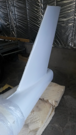
Reviving the antenna-in-tail subject, as the project fuselage is now assembled.
[img]cid:part1.B3949A7E.A7B2F84D(at)free.fr[/img]
Bob mentionned a promising "bazooka" configuration for the antenna, as the tail is too narrow to allow for a regular ground plane.
Here are some answers to your questions :
The entire fuselage is carbon. The vertical fin is integral with the fuselage but is made of glass for the installation of the antenna.
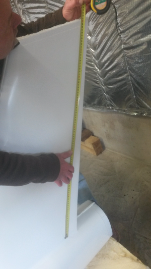
The fin height is ~ 0.9 m (35") while the carbon tail at the base is only 0.18 m (7") wide.
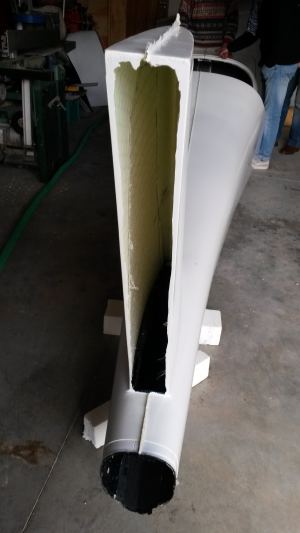
[img]cid:part2.433A4B01.02ACC99E(at)free.fr[/img][img]cid:part3.980421EA.3CA7A37E(at)free.fr[/img]
The base of the antenna will be accessible via the tail cone aperture, and crawling into the fuselage will permit limited access.
I was considering installing the radiating element in a plastic tube in the fin, so that the antenna may be easily inserted and removed.
Any suggestions as to how to devise a reasonably efficient comm antenna in the tail ?
Thanks in advance,
--
Best regards,
Gilles
http://contrails.free.fr
http://lapierre.skunkworks.free.fr
| | - The Matronics AeroElectric-List Email Forum - | | | Use the List Feature Navigator to browse the many List utilities available such as the Email Subscriptions page, Archive Search & Download, 7-Day Browse, Chat, FAQ, Photoshare, and much more:
http://www.matronics.com/Navigator?AeroElectric-List |
|
| Description: |
|
| Filesize: |
371.17 KB |
| Viewed: |
5872 Time(s) |
|
| Description: |
|
| Filesize: |
368.89 KB |
| Viewed: |
5872 Time(s) |

|
| Description: |
|
| Filesize: |
377.04 KB |
| Viewed: |
5872 Time(s) |

|
|
|
| Back to top |
|
 |
BARRY CHECK 6
Joined: 15 Mar 2011
Posts: 738
|
| Posted: Sun May 20, 2018 5:19 am Post subject: VHF antenna in the tail |
|
|
Giles:
You solved half of the antenna issue by making the vertical stab out of fiberglass.
The second issue is: What is the Torque Tube of the rudder made out of?
If it is aluminum then you have a Blanketing issue as it will mess up the radiation pattern of the antenna.
The third issue is you will need at least a 1/4 wave length Ground-plane made out of a conductive material... Aluminum or copper.
From the looks of the empennage you do not have enough area to have a ground-plane.
So, what are your options:
The most logical will also probably be the easiest - Install two home-brew antennas in the tips of the Horizontal Sab or the tips of the Elevator and co-phase them. Of course they will be horizontally phased as compared to most other antennas out there but, that is a minor inconvenience. Consider ALL those bent 1/4 wave belly mounted antennas that are bent over - - - they still work.
Here is a simple co-phased feed line:
 http://www.jonfinley.com/hobbies/harness.html
I would use BNC connectors as apposed to PL & SO connectors.
I also totally dislike CRIMP connectors. The solder ones work better and do not cut into the COAX - - EVER!
Just work out the math for the frequency you wish to use.
Barry
On Sun, May 20, 2018 at 7:43 AM, GTH <gilles.thesee(at)free.fr (gilles.thesee(at)free.fr)> wrote:
| Quote: | Le 23/12/2017 à 01:26, Robert L. Nuckolls, III a écrit :
| Quote: |
 Can you describe the physical configuration of
 the vertical fin vis-a-vis the empennage? Is
 the vertical fin detachable?
 I presume the antenna, once installed, will
 forever more be inaccessible for tweeking? Â
|
Hi Bob and all,
Reviving the antenna-in-tail subject, as the project fuselage is now assembled.
[img]cid:part1.B3949A7E.A7B2F84D(at)free.fr[/img]
Bob mentionned a promising "bazooka" configuration for the antenna, as the tail is too narrow to allow for a regular ground plane.
Here are some answers to your questions :
The entire fuselage is carbon. The vertical fin is integral with the fuselage but is made of glass for the installation of the antenna.
The fin height is ~ 0.9 m (35") while the carbon tail at the base is only 0.18 m (7") wide.
[img]cid:part2.433A4B01.02ACC99E(at)free.fr[/img][img]cid:part3.980421EA.3CA7A37E(at)free.fr[/img]
The base of the antenna will be accessible via the tail cone aperture, and crawling into the fuselage will permit limited access.
I was considering installing the radiating element in a plastic tube in the fin, so that the antenna may be easily inserted and removed.
Any suggestions as to how to devise a reasonably efficient comm antenna in the tail ?
Thanks in advance,
--
Best regards,
Gilles
http://contrails.free.fr
http://lapierre.skunkworks.free.fr
|
| | - The Matronics AeroElectric-List Email Forum - | | | Use the List Feature Navigator to browse the many List utilities available such as the Email Subscriptions page, Archive Search & Download, 7-Day Browse, Chat, FAQ, Photoshare, and much more:
http://www.matronics.com/Navigator?AeroElectric-List |
|
| Description: |
|
| Filesize: |
368.89 KB |
| Viewed: |
5869 Time(s) |

|
| Description: |
|
| Filesize: |
371.17 KB |
| Viewed: |
5869 Time(s) |

|
| Description: |
|
| Filesize: |
377.04 KB |
| Viewed: |
5869 Time(s) |

|
|
|
| Back to top |
|
|
tgmeyerster(at)gmail.com
Guest
|
| Posted: Sun May 20, 2018 5:45 am Post subject: VHF antenna in the tail |
|
|
Here is a link to Jim Wier of RST Engineering information of aircraft antennas in fiberglass airplanes and fiberglass airplane components.
http://www.rstengineering.com/rst/products/plasticplaneantenna/plasticplaneantenna.htm
I've heard Jim talk st Oshkosh numerous times.
Tim Meyer
On Sun, May 20, 2018 at 6:55 AM GTH <gilles.thesee(at)free.fr (gilles.thesee(at)free.fr)> wrote:
| Quote: | Le 23/12/2017 à 01:26, Robert L. Nuckolls, III a écrit :
| Quote: |
 Can you describe the physical configuration of
 the vertical fin vis-a-vis the empennage? Is
 the vertical fin detachable?
 I presume the antenna, once installed, will
 forever more be inaccessible for tweeking? Â
|
Hi Bob and all,
Reviving the antenna-in-tail subject, as the project fuselage is now assembled.
[img]cid:part1.B3949A7E.A7B2F84D(at)free.fr[/img]
Bob mentionned a promising "bazooka" configuration for the antenna, as the tail is too narrow to allow for a regular ground plane.
Here are some answers to your questions :
The entire fuselage is carbon. The vertical fin is integral with the fuselage but is made of glass for the installation of the antenna.
The fin height is ~ 0.9 m (35") while the carbon tail at the base is only 0.18 m (7") wide.
[img]cid:part2.433A4B01.02ACC99E(at)free.fr[/img][img]cid:part3.980421EA.3CA7A37E(at)free.fr[/img]
The base of the antenna will be accessible via the tail cone aperture, and crawling into the fuselage will permit limited access.
I was considering installing the radiating element in a plastic tube in the fin, so that the antenna may be easily inserted and removed.
Any suggestions as to how to devise a reasonably efficient comm antenna in the tail ?
Thanks in advance,
--
Best regards,
Gilles
http://contrails.free.fr
http://lapierre.skunkworks.free.fr
|
| | - The Matronics AeroElectric-List Email Forum - | | | Use the List Feature Navigator to browse the many List utilities available such as the Email Subscriptions page, Archive Search & Download, 7-Day Browse, Chat, FAQ, Photoshare, and much more:
http://www.matronics.com/Navigator?AeroElectric-List |
|
| Description: |
|
| Filesize: |
368.89 KB |
| Viewed: |
5869 Time(s) |
|
|
|
| Back to top |
|
|
user9253
Joined: 28 Mar 2008
Posts: 1908
Location: Riley TWP Michigan
|
| Posted: Sun May 20, 2018 6:26 am Post subject: Re: VHF antenna in the tail |
|
|
I would try a 1/4 wave antenna with ground plane.  Of course the small diameter tail is not the ideal shape and size for a ground plane.  But it might be good enough.  Use 4 or 6 copper tape radials (or aluminum strips) glued to the inside of the tail cone.  Or it might be easier to install a thin sheet of aluminum glued to the inside surface of the tail cone.

  If that does not work out, then try the bazooka antenna.

No antenna is perfect.  Be satisfied with good enough.
| | - The Matronics AeroElectric-List Email Forum - | | | Use the List Feature Navigator to browse the many List utilities available such as the Email Subscriptions page, Archive Search & Download, 7-Day Browse, Chat, FAQ, Photoshare, and much more:
http://www.matronics.com/Navigator?AeroElectric-List |
|
_________________
Joe Gores |
|
| Back to top |
|
|
rlborger(at)mac.com
Guest
|
| Posted: Sun May 20, 2018 7:53 am Post subject: VHF antenna in the tail |
|
|
Giles,
There are a number of comm antenna solution that do not require a ground plane. They are produced by Archer and by Advanced Aircraft Electronics. These are center-tap, full-wave antennas of various styles, shapes and prices.
See â http://www.aircraftspruce.com/search/search.php?cache=75660d9834ea34b12fc9146878e6443b&filter=&perpage=all&pageno=1
They are hidden amongst the various other antennas on the page.
In addition there are plans available on the net to craft your own copper tape/strip full wave antennas that could be used on the stern post.
I have used both the AAE and Archer antennas in composite aircraft and I have built a copper strip antenna for use with a base radio all with excellent results.
Blue skies & tailwinds,Bob BorgerEuropa XS Tri, Rotax 914, Airmaster C/S Prop (100 hrs).Little Toot Sport Biplane, Lycoming Thunderbolt AEIO-320 EXP, Hercules Prop.3705 Lynchburg Dr.Corinth, TX 76208-5331Cel: 817-992-1117rlborger(at)mac.com (rlborger(at)mac.com)On May 20, 2018, at 6:43 AM, GTH <gilles.thesee(at)free.fr (gilles.thesee(at)free.fr)> wrote:
Le 23/12/2017 à 01:26, Robert L. Nuckolls, III a écrit :
| Quote: | | Can you describe the physical configuration of the vertical fin vis-a-vis the empennage? Is the vertical fin detachable? I presume the antenna, once installed, will forever more be inaccessible for tweeking? |
Hi Bob and all, Reviving the antenna-in-tail subject, as the project fuselage is now assembled. <gljgacbhkillonjj.png> Bob mentionned a promising "bazooka" configuration for the antenna, as the tail is too narrow to allow for a regular ground plane. Here are some answers to your questions : The entire fuselage is carbon. The vertical fin is integral with the fuselage but is made of glass for the installation of the antenna. The fin height is ~ 0.9 m (35") while the carbon tail at the base is only 0.18 m (7") wide. <jnklmjhabmdjcpkm.png><ckbakhooanognjlj.png> The base of the antenna will be accessible via the tail cone aperture, and crawling into the fuselage will permit limited access. I was considering installing the radiating element in a plastic tube in the fin, so that the antenna may be easily inserted and removed. Any suggestions as to how to devise a reasonably efficient comm antenna in the tail ? Thanks in advance, -- Best regards, Gilles http://contrails.free.fr http://lapierre.skunkworks.free.fr
| | - The Matronics AeroElectric-List Email Forum - | | | Use the List Feature Navigator to browse the many List utilities available such as the Email Subscriptions page, Archive Search & Download, 7-Day Browse, Chat, FAQ, Photoshare, and much more:
http://www.matronics.com/Navigator?AeroElectric-List |
|
|
|
| Back to top |
|
|
nuckolls.bob(at)aeroelect
Guest
|
| Posted: Sun May 20, 2018 11:09 am Post subject: VHF antenna in the tail |
|
|
A
| Quote: | The base of the antenna will be accessible via the tail cone aperture, and crawling into the fuselage will permit limited access.
I was considering installing the radiating element in a plastic tube in the fin, so that the antenna may be easily inserted and removed.
Any suggestions as to how to devise a reasonably efficient comm antenna in the tail ? |
Assuming my mental image of your configuration
is accurate, consider the following.
Terminating the antenna coax in
a BNC cable connector. Then use a BNC
chassis connector to make the mechanical
transition to the antenna and "ground
planes".
The radiating portion of the antenna obviously
needs to extend up the tube. I'd go for a
chunk of RG400 with the outer jacket and
removed from about 2" of the 'antenna' segment.

Push shields back hard exposing center conductor

Cut off center conductor

Stretch the braids out and 'tin' the last
1/4" or so with solder.

Mount chassis BNC connector to 'ground plane'.
Suggest copper sheet, 1/2" minimum to as wide as
you can fit into the tail cone. The chassis
connector can be spot-soldered to copper
sheet.

Repeat on opposite side . . .

If copper sheet is not readily available,
aluminum can be used. If the aluminum option
is selected, use the star-washer supplied with
the connector to improve electrical interface
with the ground-plane.
The 'radials' are 1/4-wave (24") extending forward
on each side of tailcone.

If you have access to an antenna analyzer (MFJ259
or similar), you can survey the installed
antenna for resonance. I suspect you'll find
that it resonates a bit low in frequency due to
proximity effects of the rudder post.
Trim antenna 1/4" at a time until SWR
minimizes at 126.5 MHz.
If post installation evaluation is impractical
or impossible, then shorten the antenna by about
5% . . . make it 23 inches.
Does this look 'doable' on your project?
The photos above have been posted at . . .
https://goo.gl/9NaAK1
Bob . . .
| | - The Matronics AeroElectric-List Email Forum - | | | Use the List Feature Navigator to browse the many List utilities available such as the Email Subscriptions page, Archive Search & Download, 7-Day Browse, Chat, FAQ, Photoshare, and much more:
http://www.matronics.com/Navigator?AeroElectric-List |
|
|
|
| Back to top |
|
|
user9253
Joined: 28 Mar 2008
Posts: 1908
Location: Riley TWP Michigan
|
| Posted: Sun May 20, 2018 12:30 pm Post subject: Re: VHF antenna in the tail |
|
|
Bob, it is not clear from the photo, but is the 23" antenna braid soldered to the center pin on the BNC chassis connector? I assume coax is used for the radiating element instead of a wire because the coax is fatter and will give a wider bandwidth than, say, a 14 awg wire.
| | - The Matronics AeroElectric-List Email Forum - | | | Use the List Feature Navigator to browse the many List utilities available such as the Email Subscriptions page, Archive Search & Download, 7-Day Browse, Chat, FAQ, Photoshare, and much more:
http://www.matronics.com/Navigator?AeroElectric-List |
|
_________________
Joe Gores |
|
| Back to top |
|
|
nuckolls.bob(at)aeroelect
Guest
|
| Posted: Sun May 20, 2018 1:58 pm Post subject: VHF antenna in the tail |
|
|
At 03:30 PM 5/20/2018, you wrote:
| Quote: | --> AeroElectric-List message posted by: "user9253" <fransew(at)gmail.com>
Bob, it is not clear from the photo, but is the 23" antenna braid soldered to the center pin on the BNC chassis connector? |
Yes. The center conductor in the radiator is not
a participant in the design.
| Quote: | I assume coax is used for the radiating element instead of a wire because the coax is fatter and will give a wider bandwidth than, say, a 14 awg wire.
|
The design goal is to make a flexure-resistant connection
between the connector and the radiator. The dual-shield
configuration on RG400 offers an attractive solution
for achieving this goal . . . leaving it 1/4-wave
long finishes out the radiator with a single soldered
joint.
Bob . . .
| | - The Matronics AeroElectric-List Email Forum - | | | Use the List Feature Navigator to browse the many List utilities available such as the Email Subscriptions page, Archive Search & Download, 7-Day Browse, Chat, FAQ, Photoshare, and much more:
http://www.matronics.com/Navigator?AeroElectric-List |
|
|
|
| Back to top |
|
|
Peter(at)sportingaero.com
Guest
|
| Posted: Sun May 20, 2018 1:59 pm Post subject: VHF antenna in the tail |
|
|
Have you considered one of these?
http://www.dolba.de/antennenloesungen/funk-antenne-bd5/
Fitted to many German gliders, bonded to the fin structure, most how have glass fiber fins to allow VHF, txpdr & flarm antennas all to be hidden inside.
Peter
From: owner-aeroelectric-list-server(at)matronics.com <owner-aeroelectric-list-server(at)matronics.com> On Behalf Of GTH
Sent: 20 May 2018 12:43
To: aeroelectric-list(at)matronics.com
Subject: Re: VHF antenna in the tail
Le 23/12/2017 à 01:26, Robert L. Nuckolls, III a écrit :
| Quote: |
Can you describe the physical configuration of
the vertical fin vis-a-vis the empennage? Is
the vertical fin detachable?
I presume the antenna, once installed, will
forever more be inaccessible for tweeking? |
Hi Bob and all,
Reviving the antenna-in-tail subject, as the project fuselage is now assembled.
[img]cid:image001.png(at)01D3F08D.EA11DAD0[/img]
Bob mentionned a promising "bazooka" configuration for the antenna, as the tail is too narrow to allow for a regular ground plane.
Here are some answers to your questions :
The entire fuselage is carbon. The vertical fin is integral with the fuselage but is made of glass for the installation of the antenna.
The fin height is ~ 0.9 m (35") while the carbon tail at the base is only 0.18 m (7") wide.
[img]cid:image002.png(at)01D3F08D.EA11DAD0[/img][img]cid:image003.png(at)01D3F08D.EA11DAD0[/img]
The base of the antenna will be accessible via the tail cone aperture, and crawling into the fuselage will permit limited access.
I was considering installing the radiating element in a plastic tube in the fin, so that the antenna may be easily inserted and removed.
Any suggestions as to how to devise a reasonably efficient comm antenna in the tail ?
Thanks in advance,
--
Best regards,
Gilles
http://contrails.free.fr
http://lapierre.skunkworks.free.fr
| | - The Matronics AeroElectric-List Email Forum - | | | Use the List Feature Navigator to browse the many List utilities available such as the Email Subscriptions page, Archive Search & Download, 7-Day Browse, Chat, FAQ, Photoshare, and much more:
http://www.matronics.com/Navigator?AeroElectric-List |
|
| Description: |
|
| Filesize: |
371.17 KB |
| Viewed: |
5847 Time(s) |

|
| Description: |
|
| Filesize: |
368.89 KB |
| Viewed: |
5847 Time(s) |

|
| Description: |
|
| Filesize: |
377.04 KB |
| Viewed: |
5847 Time(s) |
|
|
|
| Back to top |
|
|
nuckolls.bob(at)aeroelect
Guest
|
| Posted: Sun May 20, 2018 3:32 pm Post subject: VHF antenna in the tail |
|
|
At 04:57 PM 5/20/2018, you wrote:
Do you know anyone who has installed this antenna on
an OBAM aircraft? It's not clear from the image
just how it installs. The website had no links to
installation manuals that I could find.
The SWR plot is impressive . . . but SWR and
efficiency are two separate things. I've dropped
them an email requesting more details.
Bob . . .
| | - The Matronics AeroElectric-List Email Forum - | | | Use the List Feature Navigator to browse the many List utilities available such as the Email Subscriptions page, Archive Search & Download, 7-Day Browse, Chat, FAQ, Photoshare, and much more:
http://www.matronics.com/Navigator?AeroElectric-List |
|
|
|
| Back to top |
|
|
nuckolls.bob(at)aeroelect
Guest
|
| Posted: Mon May 21, 2018 8:05 am Post subject: VHF antenna in the tail |
|
|
Had a dentist appointment 33 miles away this

 morning . . . did some 'asphalt engineering'

 on this thread . . .


 I occurred to me that the design might be more

 easily fabricated, installed and maintained if

 the chassis connector originally suggested were

 replaced with a BNCF->BNCF bulkhead feed thru

 like:Bu


 https://goo.gl/XDTtod


 The feed line from the transceiver would be

 terminated in a BNCM cable connector as

 before. Instead of terminating the radiator

 with a solder joint at the connector, it too

 would be fitted with a BNCM cable connector

 so that it could be detached without disturbing

 the ground plane.


 This style of connector seems a likely

 candidate:


 https://goo.gl/VLjQXH


 Solder a short stub of 20AWG wire into the

 center pin to facilitate connection to the end

 of the radiator's 'flexy' section. Cover with

 heat shrink. With the pin fully seated in the

 connector, back-fill the connector shell with

 JB weld or other epoxy. The connector clamp

 ring, gasket and compression nut are discarded.


 By the way, the ground plane doesn't need to

 be tucked up tight against the bottom of the

 radiator conduit. Several inches of radiator

 could be used to jump a short gap from bottom

 of conduit to the ground plane without serious

 effect.


   Bob . . .
| | - The Matronics AeroElectric-List Email Forum - | | | Use the List Feature Navigator to browse the many List utilities available such as the Email Subscriptions page, Archive Search & Download, 7-Day Browse, Chat, FAQ, Photoshare, and much more:
http://www.matronics.com/Navigator?AeroElectric-List |
|
|
|
| Back to top |
|
|
gilles.thesee(at)free.fr
Guest
|
| Posted: Tue May 22, 2018 4:35 am Post subject: VHF antenna in the tail |
|
|
Le 20/05/2018 à 16:26, user9253 a écrit :
| Quote: | | Quote: | --> AeroElectric-List message posted by: "user9253" <fransew(at)gmail.com> (fransew(at)gmail.com)
I would try a 1/4 wave antenna with ground plane. Of course the small diameter tail is not the ideal shape and size for a ground plane. But it might be good enough. |
|
Joe and all,
Thank you to all who responded.
I guess I'll follow your advice and build a mock-up of the "sub-optimal" ground plane. And then conduct some experiments - for instance calling aircraft flying nearby etc.
As for other informations, the all moving tailplane is to be carbon fiber, and the carbon tips are already fabricated.
Interesting info from Jim Weir, but of use for *glass* airplanes. Also our project has a tiny vertical fin and could not accomodate a 1/2 wave antenna.
Do not hesitate to keep sending advices !
Will keep you posted,
--
Best regards,
Gilles
http://contrails.free.fr
http://lapierre.skunkworks.free.fr
| | - The Matronics AeroElectric-List Email Forum - | | | Use the List Feature Navigator to browse the many List utilities available such as the Email Subscriptions page, Archive Search & Download, 7-Day Browse, Chat, FAQ, Photoshare, and much more:
http://www.matronics.com/Navigator?AeroElectric-List |
|
|
|
| Back to top |
|
|
nuckolls.bob(at)aeroelect
Guest
|
| Posted: Tue May 22, 2018 8:13 am Post subject: VHF antenna in the tail |
|
|
At 07:33 AM 5/22/2018, you wrote:
| Quote: | Le 20/05/2018 à 16:26, user9253 a écrit :
| Quote: |
| Quote: | --> AeroElectric-List message posted by:
"user9253"
<fransew(at)gmail.com> (fransew(at)gmail.com)
I would try a 1/4 wave antenna with ground plane. Of course the
small diameter tail is not the ideal shape and size for a ground
plane. But it might be good
enough.[/i] |
|
Joe and all,
Thank you to all who responded.
I guess I'll follow your advice and build a mock-up of the "sub-optimal" ground plane. And then conduct some experiments - for instance calling aircraft flying nearby etc. |
the most significant benchmark for performance
will be achieving lowest possible SWR over
the frequencies of interest. As long as the
majority of your radiating conductor is oriented
vertically in the conduit, you're going to
experience adequate performance.
Jim Wier published a study on various factors
influencing line of sight communications about
20 years ago . . . probably got a copy around
here somewhere . . .
The upshot of his piece was the realization
that it takes very little power to communicate
over large distances assuming line of sight
and serviceable antenna efficiencies.
All other things held constant, you'll probably
observe no difference in utility between a
laboratory grade antenna and a relatively
poor DIY product. The tallest and most tractable
hurdles are getting your antenna to accept the
transceiver's power and minimizing lossy (high
resistance) features in the design.
This thread should probably include some exploration
of another option. Some years ago, there was a product
marketed as the "Miracle Air Whip". One of several
reviews can be see here. https://goo.gl/WQyNmu
We had some discussion about the product here on
the List. I published a couple of images . . .
https://goo.gl/ssf7CG
https://goo.gl/upHYTB
Variations on this theme have been proposed and
published in the ham radio venues for decades.
https://goo.gl/zSQpu1
This design will be about 35" long . . . how long
is the conduit extending up the vertical fin?
While rudimentary in the physics of design and performance,
the practical solution needs to select materials
and assembly methods that are suited for the
less than gentle environment of an airplane's
tail cone.
Bob . . .
| | - The Matronics AeroElectric-List Email Forum - | | | Use the List Feature Navigator to browse the many List utilities available such as the Email Subscriptions page, Archive Search & Download, 7-Day Browse, Chat, FAQ, Photoshare, and much more:
http://www.matronics.com/Navigator?AeroElectric-List |
|
|
|
| Back to top |
|
|
|
|
You cannot post new topics in this forum
You cannot reply to topics in this forum
You cannot edit your posts in this forum
You cannot delete your posts in this forum
You cannot vote in polls in this forum
You cannot attach files in this forum
You can download files in this forum
|
Powered by phpBB © 2001, 2005 phpBB Group
|

