 |
Matronics Email Lists
Web Forum Interface to the Matronics Email Lists
|
| View previous topic :: View next topic |
| Author |
Message |
Eric Page
Joined: 15 Feb 2017
Posts: 244
|
 Posted: Sun Oct 29, 2017 7:10 pm Post subject: Re: Constructing an automatic RCA video camera feed splitte Posted: Sun Oct 29, 2017 7:10 pm Post subject: Re: Constructing an automatic RCA video camera feed splitte |
 |
|
| alec(at)alecmyers.com wrote: | 201 instructions, now, and still 9 bytes of data. So you saved 19 instructions by changing IC.
I’ve run it through PICSIM as best I can; hardware would be the next step. Unfortunately I don’t have any trash PCBs for 8-pin PICs. |
Beauty!
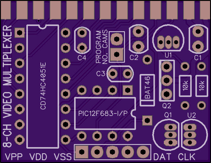
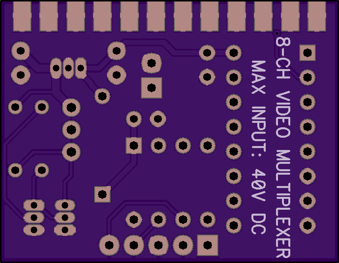
I've got the schematic (PDF attached) and a fist pass at the board layout complete.
I exchanged a few questions/answers with a TI engineer about using the CD74HC4051E, and he told me the main "gotcha" with the part is applying a signal to an input before the IC is powered up. Apparently there's a path from the inputs to Vdd until the internal FETs are properly biased. To eliminate this possibility, I added a small circuit (bottom right corner of the schematic) consisting of a power-on reset (POR) IC and a couple of MOSFETs. The POR watches the +5V rail, and as soon as 1V is reached it begins to hold Q1 off, thus allowing Q2 to be held off by R2. Once the +5V rail reaches 4.85V and a 150mS delay elapses, the reset signal is released, Q1 turns on, turning on Q2 and allowing bus power to reach the cameras. If the +5V rail falls below 4.85V, the cameras are immediately shut off. Assuming the cameras consume ~100mA each, it should be no problem to power eight of them through a single D-Sub pin.
The PCB is designed to fit between the two rows of solder cups on a DB-25 connector and be soldered in place. Q2 will probably have to have its legs bent so it lays back, over the BAT46 diode.
I'd say we're about done for now. Once we see how Wade's RCA-to-USB converter and EFIS handle being switched between camera feeds, and Bob checks the camera output signal, we'll know if any changes are necessary or if we can go ahead with a hardware prototype.
Eric
Top side of PCB:
Bottom side of PCB:
| | - The Matronics AeroElectric-List Email Forum - | | | Use the List Feature Navigator to browse the many List utilities available such as the Email Subscriptions page, Archive Search & Download, 7-Day Browse, Chat, FAQ, Photoshare, and much more:
http://www.matronics.com/Navigator?AeroElectric-List |
|
| Description: |
|

Download |
| Filename: |
8-Ch Vid Cam Mux (Rev C).pdf |
| Filesize: |
109.87 KB |
| Downloaded: |
508 Time(s) |
|
|
| Back to top |
|
 |
alec(at)alecmyers.com
Guest
|
| Posted: Sun Oct 29, 2017 7:18 pm Post subject: Constructing an automatic RCA video camera feed splitter |
|
|
I didn’t get a schematic attached.
But - if you have a PIC, isn’t it a better idea to get the PIC to do the POR? Even if we can’t contrive a way to spare a pin with an 8 pin PIC ou could go back to the 14 pin PIC at no extra cost, and have plenty of IO pins, comparators etc. No extra cost and you save the POR IC.
On Oct 29, 2017, at 11:10 PM, Eric Page <edpav8r(at)yahoo.com> wrote:
alec(at)alecmyers.com wrote:
| Quote: | 201 instructions, now, and still 9 bytes of data. So you saved 19 instructions by changing IC.
Iâve run it through PICSIM as best I can; hardware would be the next step. Unfortunately I donât have any trash PCBs for 8-pin PICs.
|
Beauty!
I've got the schematic (PDF attached) and a fist pass at the board layout complete.
I exchanged a few questions/answers with a TI engineer about using the CD74HC4051E, and he told me the main "gotcha" with the part is applying a signal to an input before the IC is powered up. Apparently there's a path from the inputs to Vdd until the internal FETs are properly biased. To eliminate this possibility, I added a small circuit (bottom right corner of the schematic) consisting of a power-on reset (POR) IC and a couple of MOSFETs. The POR watches the +5V rail, and as soon as 1V is reached it begins to hold Q1 off, thus allowing Q2 to be held off by R2. Once the +5V rail reaches 4.85V and a 150mS delay elapses, the reset signal is released, Q1 turns on, turning on Q2 and allowing bus power to reach the cameras. If the +5V rail falls below 4.85V, the cameras are immediately shut off. Assuming the cameras consume ~100mA each, it should be no problem to power eight of them through a single D-Sub pin.
The PCB is designed to fit between the two rows of solder cups on a DB-25 connector and be soldered in place. Q2 will probably have to have its legs bent so it lays back, over the BAT46 diode.
I'd say we're about done for now. Once we see how Wade's RCA-to-USB converter and EFIS handle being switched between camera feeds, and Bob checks the camera output signal, we'll know if any changes are necessary or if we can go ahead with a hardware prototype.
Eric
Top side of PCB:
Bottom side of PCB:
Read this topic online here:
http://forums.matronics.com/viewtopic.php?p=473955#473955
Attachments:
http://forums.matronics.com//files/8_ch_vid_cam_mux_rev_c_213.pdf
| | - The Matronics AeroElectric-List Email Forum - | | | Use the List Feature Navigator to browse the many List utilities available such as the Email Subscriptions page, Archive Search & Download, 7-Day Browse, Chat, FAQ, Photoshare, and much more:
http://www.matronics.com/Navigator?AeroElectric-List |
|
|
|
| Back to top |
|
|
Eric Page
Joined: 15 Feb 2017
Posts: 244
|
| Posted: Sun Oct 29, 2017 7:56 pm Post subject: Re: Constructing an automatic RCA video camera feed splitte |
|
|
| alec(at)alecmyers.com wrote: | | I didn’t get a schematic attached. |
Apparently the server doesn't include attachments with the email echo.
See: http://forums.matronics.com//files/8_ch_vid_cam_mux_rev_c_213.pdf
| Quote: | | But - if you have a PIC, isn’t it a better idea to get the PIC to do the POR? Even if we can’t contrive a way to spare a pin with an 8 pin PIC ou could go back to the 14 pin PIC at no extra cost, and have plenty of IO pins, comparators etc. No extra cost and you save the POR IC. |
This sounds like a reasonable idea. Can the PIC12F683 monitor its own Vdd, or is a separate pin required as an input for the comparator funciton?
The camera power is switched through a P-Ch MOSFET, so it's held OFF automatically by a pull-up resistor. If the PIC can pull the MOSFET gate to ground when Vdd exceeds a threshold voltage, then the POR is unnecessary, as is the N-Ch MOSFET to switch the P-Ch.
Since the MOSFET's gate won't be bothered by 12V, we could use the Vpp pin to switch it during normal operation. If a separate pin is required for the comparator input, then we use a 14-pin PIC and have pins to spare.
Eric
| | - The Matronics AeroElectric-List Email Forum - | | | Use the List Feature Navigator to browse the many List utilities available such as the Email Subscriptions page, Archive Search & Download, 7-Day Browse, Chat, FAQ, Photoshare, and much more:
http://www.matronics.com/Navigator?AeroElectric-List |
|
|
|
| Back to top |
|
|
Eric Page
Joined: 15 Feb 2017
Posts: 244
|
| Posted: Sun Oct 29, 2017 8:01 pm Post subject: Re: Constructing an automatic RCA video camera feed splitte |
|
|
| Eric Page wrote: | | If the PIC can pull the MOSFET gate to ground when Vdd exceeds a threshold voltage, then the POR is unnecessary, as is the N-Ch MOSFET to switch the P-Ch. |
Never mind this sentence; that won't work. The P-Ch gate has to be pulled up to its source voltage, which is too high for a PIC pin. So, an N-Ch is still needed to control the P-Ch. This would reverse the PIC output logic: Vdd low - output low, Vdd normal - output high.
Eric
| | - The Matronics AeroElectric-List Email Forum - | | | Use the List Feature Navigator to browse the many List utilities available such as the Email Subscriptions page, Archive Search & Download, 7-Day Browse, Chat, FAQ, Photoshare, and much more:
http://www.matronics.com/Navigator?AeroElectric-List |
|
|
|
| Back to top |
|
|
alec(at)alecmyers.com
Guest
|
| Posted: Sun Oct 29, 2017 8:22 pm Post subject: Constructing an automatic RCA video camera feed splitter |
|
|
The brownout reset of the PIC sounds like the right sort of idea, but it holds in reset only until the Vdd rises to between 2 and 2.2V. One could run the PIC from 2.5V derived from a 5V supply with a zener diode/resistor network to hold it off until the supply voltage reaches 4.5V, but then the maximum pin output voltage isn’t guaranteed to be higher than 1.8V, which won’t drive the switching inputs of the multiplexer. I don’t think I’m cunning enough to make that work with an 8 pin device.
If you have room to go back to the 16f18323, it has an internal 1.024V fixed voltage reference and a comparator module. If we set the voltage reference as an internal input to the comparator, and connect the centre of a two resistor potential divider from Vdd to the external input of the comparator then you can easily detect when Vdd rises above an arbitrary threshold. Then you can have a logic output some chosen delay after the supply voltage rises above an arbitrary threshold.
On Oct 29, 2017, at 11:56 PM, Eric Page <edpav8r(at)yahoo.com> wrote:
alec(at)alecmyers.com wrote:
| Quote: | I didnât get a schematic attached.
|
Apparently the server doesn't include attachments with the email echo.
See: http://forums.matronics.com//files/8_ch_vid_cam_mux_rev_c_213.pdf
| Quote: | But - if you have a PIC, isnât it a better idea to get the PIC to do the POR? Even if we canât contrive a way to spare a pin with an 8 pin PIC ou could go back to the 14 pin PIC at no extra cost, and have plenty of IO pins, comparators etc. No extra cost and you save the POR IC.
|
This sounds like a reasonable idea. Can the PIC12F683 monitor its own Vdd, or is a separate pin required as an input for the comparator funciton?
The camera power is switched through a P-Ch MOSFET, so it's held OFF automatically by a pull-up resistor. If the PIC can pull the MOSFET gate to ground when Vdd exceeds a threshold voltage, then the POR is unnecessary, as is the N-Ch MOSFET to switch the P-Ch.
Since the MOSFET's gate won't be bothered by 12V, we could use the Vpp pin to switch it during normal operation. If a separate pin is required for the comparator input, then we use a 14-pin PIC and have pins to spare.
Eric
Read this topic online here:
http://forums.matronics.com/viewtopic.php?p=473957#473957
| | - The Matronics AeroElectric-List Email Forum - | | | Use the List Feature Navigator to browse the many List utilities available such as the Email Subscriptions page, Archive Search & Download, 7-Day Browse, Chat, FAQ, Photoshare, and much more:
http://www.matronics.com/Navigator?AeroElectric-List |
|
|
|
| Back to top |
|
|
rickofudall
Joined: 19 Sep 2009
Posts: 1392
Location: Udall, KS, USA
|
| Posted: Mon Oct 30, 2017 3:04 pm Post subject: Constructing an automatic RCA video camera feed splitter |
|
|
If I understand this project, it's just switching between cameras that are making a continual feed. How much more difficult would it be to not only switch between cameras but turn the camera off and on, too?I found this little guy at Gearbest (although it was only $33.41 when I bought it just last month):
https://www.gearbest.com/fpv-system/pp_219405.html
Amazing little camera that has a socket for a micro SD of up to 32 Gb. Even with that much storage it's only good for about 120 minutes of 1080P video. It seems like a lot until you consider how much is wasted in taxi and transit to the area where you want to film. As my trike is slow (42 mph cruise) that can amount to a quarter to half of the storage gone before I get to where I want to actually start recording. If the price comes back down again I'd like to have one on each wingtip, another on a boom from the nose, and a fourth on a drogue ( https://www.youtube.com/watch?v=_9hX5qY_nO8 ) I've been using GoPro clones but being able to turn the HD19 on and off as I want would be much better.
Rick Girard
On Sun, Oct 29, 2017 at 10:16 PM, Alec Myers <alec(at)alecmyers.com (alec(at)alecmyers.com)> wrote:
| Quote: | --> AeroElectric-List message posted by: Alec Myers <alec(at)alecmyers.com (alec(at)alecmyers.com)>
I didn’t get a schematic attached.
But - if you have a PIC, isn’t it a better idea to get the PIC to do the POR? Even if we can’t contrive a way to spare a pin with an 8 pin PIC ou could go back to the 14 pin PIC at no extra cost, and have plenty of IO pins, comparators etc. No extra cost and you save the POR IC.
On Oct 29, 2017, at 11:10 PM, Eric Page <edpav8r(at)yahoo.com (edpav8r(at)yahoo.com)> wrote:
--> AeroElectric-List message posted by: "Eric Page" <edpav8r(at)yahoo.com (edpav8r(at)yahoo.com)>
alec(at)alecmyers.com wrote:
> 201 instructions, now, and still 9 bytes of data. So you saved 19 instructions by changing IC.
>
> I’ve run it through PICSIM as best I can; hardware would be the next step. Unfortunately I don’t have any trash PCBs for 8-pin PICs.
Beauty!
I've got the schematic (PDF attached) and a fist pass at the board layout complete.
I exchanged a few questions/answers with a TI engineer about using the CD74HC4051E, and he told me the main "gotcha" with the part is applying a signal to an input before the IC is powered up. Apparently there's a path from the inputs to Vdd until the internal FETs are properly biased. To eliminate this possibility, I added a small circuit (bottom right corner of the schematic) consisting of a power-on reset (POR) IC and a couple of MOSFETs. The POR watches the +5V rail, and as soon as 1V is reached it begins to hold Q1 off, thus allowing Q2 to be held off by R2. Once the +5V rail reaches 4.85V and a 150mS delay elapses, the reset signal is released, Q1 turns on, turning on Q2 and allowing bus power to reach the cameras. If the +5V rail falls below 4.85V, the cameras are immediately shut off. Assuming the cameras consume ~100mA each, it should be no problem to power eight of them through a single D-Sub pin.
The PCB is designed to fit between the two rows of solder cups on a DB-25 connector and be soldered in place. Q2 will probably have to have its legs bent so it lays back, over the BAT46 diode.
I'd say we're about done for now. Once we see how Wade's RCA-to-USB converter and EFIS handle being switched between camera feeds, and Bob checks the camera output signal, we'll know if any changes are necessary or if we can go ahead with a hardware prototype.
Eric
Top side of PCB:
Bottom side of PCB:
Read this topic online here:
http://forums.matronics.com/viewtopic.php?p=473955#473955
Attachments:
http://forums.matronics.com//files/8_ch_vid_cam_mux_rev_c_213.pdf
====================================
-
Electric-List" rel="noreferrer" target="_blank">http://www.matronics.com/Navigator?AeroElectric-List
====================================
FORUMS -
eferrer" target="_blank">http://forums.matronics.com
====================================
WIKI -
errer" target="_blank">http://wiki.matronics.com
====================================
b Site -
-Matt Dralle, List Admin.
rel="noreferrer" target="_blank">http://www.matronics.com/contribution
====================================
|
--
“Blessed are the cracked, for they shall let in the light.” Groucho Marx
| | - The Matronics AeroElectric-List Email Forum - | | | Use the List Feature Navigator to browse the many List utilities available such as the Email Subscriptions page, Archive Search & Download, 7-Day Browse, Chat, FAQ, Photoshare, and much more:
http://www.matronics.com/Navigator?AeroElectric-List |
|
_________________
The smallest miracle right in front of you is enough to make you happy.... |
|
| Back to top |
|
|
Eric Page
Joined: 15 Feb 2017
Posts: 244
|
| Posted: Mon Oct 30, 2017 4:06 pm Post subject: Re: Constructing an automatic RCA video camera feed splitte |
|
|
| rickofudall wrote: | | If I understand this project, it's just switching between cameras that are making a continual feed. |
Correct.
| Quote: | | How much more difficult would it be to not only switch between cameras but turn the camera off and on, too? |
In principle, trivial, but it would certainly complicate the design of what we're doing in response to Wade's request.
What exactly is it that you want to accomplish? I presume that on a trike you're not feeding your cameras into an EFIS display, but rather letting them record to memory, then editing the recorded video later.
Do you want to be able to power the cameras ON/OFF remotely to save battery charge AND be able to toggle recording, or is it OK to have the cameras ON for the whole flight, and just be able to remotely toggle recording when desired?
Without opening one of those cameras it's hard to know for sure, but judging by the buttons on them, it looks like you should be able to wire an additional switch parallel to the RECORD button and place it in a convenient location. If you want to control four cameras, a small board (1" x 2-1/2" should do) with four tactile switches could be mounted wherever you like and wired to the cameras. You could open each camera and install a pigtail from the RECORD switch to a two-pin connector outside the camera body, then route a wire pair with matching connector to the switch panel.
Unless I've misunderstood what you want, I don't think any electronics would be required.
Eric
| | - The Matronics AeroElectric-List Email Forum - | | | Use the List Feature Navigator to browse the many List utilities available such as the Email Subscriptions page, Archive Search & Download, 7-Day Browse, Chat, FAQ, Photoshare, and much more:
http://www.matronics.com/Navigator?AeroElectric-List |
|
|
|
| Back to top |
|
|
Airdog77
Joined: 24 Nov 2013
Posts: 80
Location: Northern Virginia
|
| Posted: Tue Oct 31, 2017 12:52 am Post subject: Re: Constructing an automatic RCA video camera feed splitte |
|
|
Eric,
| Quote: | | Once we see how Wade's RCA-to-USB converter and EFIS handle being switched between camera feeds |
FYI - I should be done with the final checks on my panel/EFIS by the end of this week, and ready to start testing video NLT end of next week.
Cheers,
Wade
| | - The Matronics AeroElectric-List Email Forum - | | | Use the List Feature Navigator to browse the many List utilities available such as the Email Subscriptions page, Archive Search & Download, 7-Day Browse, Chat, FAQ, Photoshare, and much more:
http://www.matronics.com/Navigator?AeroElectric-List |
|
_________________
Airdog
Wade Parton
Building Long-EZ N916WP
www.longezpush.com |
|
| Back to top |
|
|
Eric Page
Joined: 15 Feb 2017
Posts: 244
|
| Posted: Tue Oct 31, 2017 5:30 am Post subject: Re: Constructing an automatic RCA video camera feed splitte |
|
|
| Airdog77 wrote: | | FYI - I should be done with the final checks on my panel/EFIS by the end of this week, and ready to start testing video NLT end of next week. |
I hope all the geek chatter hasn't created a sense of urgency! There's no rush; take your time... ;-}
Eric
P.S. Alec and I have begun direct email comms to avoid spamming the List with endless back-and-forth about PCB layout and PIC programming. I promise no functional or interface changes without consultation here.
| | - The Matronics AeroElectric-List Email Forum - | | | Use the List Feature Navigator to browse the many List utilities available such as the Email Subscriptions page, Archive Search & Download, 7-Day Browse, Chat, FAQ, Photoshare, and much more:
http://www.matronics.com/Navigator?AeroElectric-List |
|
|
|
| Back to top |
|
|
Airdog77
Joined: 24 Nov 2013
Posts: 80
Location: Northern Virginia
|
|
| Back to top |
|
|
Airdog77
Joined: 24 Nov 2013
Posts: 80
Location: Northern Virginia
|
| Posted: Thu Nov 16, 2017 9:44 pm Post subject: Re: Constructing an automatic RCA video camera feed splitte |
|
|
Eric & Alec,
| Quote: | | Once we hear from Wade that his EFIS and video adapter handle the camera feed switching OK, I'll edit the schematic and work on a board layout. |
Just wanted to let you guys know I hooked up 3 cameras to the switching unit that you recommended Eric and fed it into the GRT EFIS via the switching unit's RCA jack out into the USB adapter.
The switching worked fine, albeit their is a VERY brief (less than half a second) skewing of the screen as it goes from one video input to the other. You have to be looking right at it to see it.
Again, it all looked fine to me. If we could eliminate the skewing it'd be nice, but definitely not a showstopper.
Cheers,
Wade
| | - The Matronics AeroElectric-List Email Forum - | | | Use the List Feature Navigator to browse the many List utilities available such as the Email Subscriptions page, Archive Search & Download, 7-Day Browse, Chat, FAQ, Photoshare, and much more:
http://www.matronics.com/Navigator?AeroElectric-List |
|
_________________
Airdog
Wade Parton
Building Long-EZ N916WP
www.longezpush.com |
|
| Back to top |
|
|
Eric Page
Joined: 15 Feb 2017
Posts: 244
|
| Posted: Thu Nov 16, 2017 10:18 pm Post subject: Re: Constructing an automatic RCA video camera feed splitte |
|
|
| Airdog77 wrote: | | The switching worked fine, albeit their is a VERY brief (less than half a second) skewing of the screen as it goes from one video input to the other. You have to be looking right at it to see it. |
I'm glad to hear it works OK and the EFIS doesn't lose sync on the video signal. Thinking out loud here... the brief skewing you see may have something to do with the mechanical switch. Perhaps it's a break-before-make type, so for several milliseconds there's no signal present. With the switching done electronically, the loss of signal will be reduced to a few tens of nanoseconds, so that issue *may* disappear.
Eric
| | - The Matronics AeroElectric-List Email Forum - | | | Use the List Feature Navigator to browse the many List utilities available such as the Email Subscriptions page, Archive Search & Download, 7-Day Browse, Chat, FAQ, Photoshare, and much more:
http://www.matronics.com/Navigator?AeroElectric-List |
|
|
|
| Back to top |
|
|
|
|
You cannot post new topics in this forum
You cannot reply to topics in this forum
You cannot edit your posts in this forum
You cannot delete your posts in this forum
You cannot vote in polls in this forum
You cannot attach files in this forum
You can download files in this forum
|
Powered by phpBB © 2001, 2005 phpBB Group
|

